Non-centrosymmetrical H-shaped finned tube and finned tube heat exchange tube bundle

A non-centrosymmetric, finned tube technology, used in tubular elements, heat exchange equipment, lighting and heating equipment, etc., can solve the problems of blockage of heat exchange equipment, dust accumulation, low thermal conductivity, etc., to reduce volume and steel consumption. , The effect of reducing the total manufacturing cost and improving the heat exchange performance

Active Publication Date: 2015-04-08
XI AN JIAOTONG UNIV
View PDF7 Cites 12 Cited by
  • Summary
  • Abstract
  • Description
  • Claims
  • Application Information

AI Technical Summary

Problems solved by technology

The contact area between the flue gas flow on the windward side and the base pipe and fins is larger than that on the leeward side, and the heat transfer performance of the fins on the leeward side, which is prone to air separation, is low and prone to dust accumulation
Due to the low thermal cond

Method used


Image

  • Non-centrosymmetrical H-shaped finned tube and finned tube heat exchange tube bundle
  • Non-centrosymmetrical H-shaped finned tube and finned tube heat exchange tube bundle
  • Non-centrosymmetrical H-shaped finned tube and finned tube heat exchange tube bundle

Examples


Embodiment 1

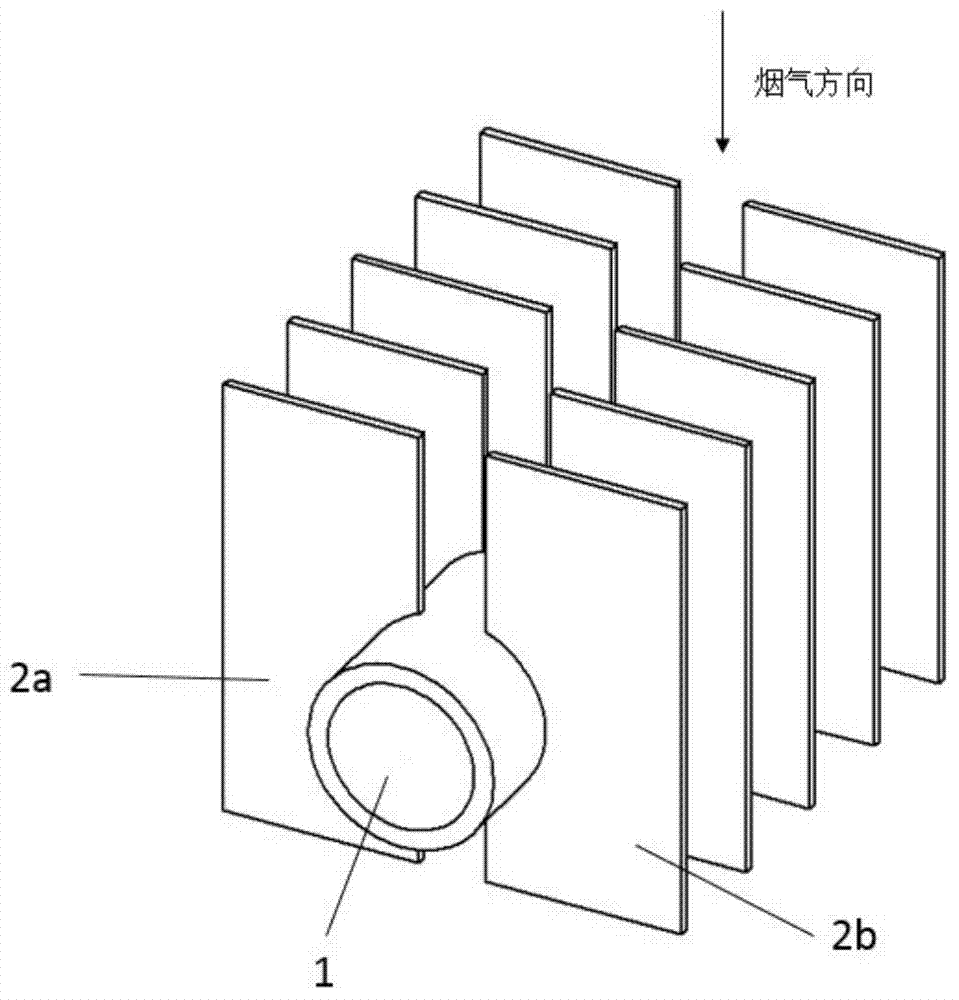
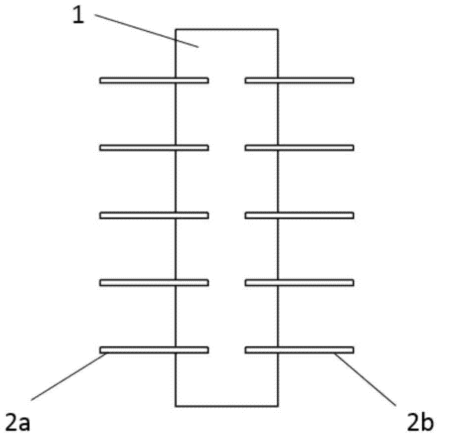
[0036] figure 1 It is a schematic structural diagram of Embodiment 1 of the present invention, the shape of the fins is rectangular, and the number of base tubes is one.

[0037] like figure 1 As shown, the non-centrosymmetric H-shaped finned tube includes a base tube portion 1 and a finned portion 2 . There is a flowing heat exchange working medium in the base pipe part 1 . The fin part 2 includes a plurality of fin groups composed of left quadrilateral fins 2a and right quadrilateral fins 2b, and the fin groups are arranged parallel to each other on the outer wall of the base pipe part 1 along the axial direction of the base pipe part 1 at a certain interval. superior.

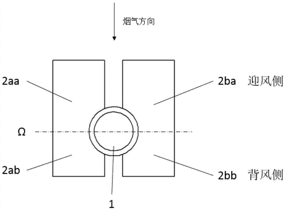
[0038] figure 2 It is the front view of Embodiment 1 of the present invention.

[0039] Taking the plane Ω passing through the axis of the base pipe 1 and perpendicular to the direction of flue gas flow as the interface, the left quadrilateral fin 2a is divided into the left windward side part 2aa and ...

Embodiment 2

[0044] Figure 5 It is a schematic structural diagram of Embodiment 2 of the present invention, the shape of the fins is trapezoidal, Image 6 It is the front view of Embodiment 2 of the present invention. The short side of the fins and the incoming flow direction of the flue gas vary in the range of 45° to 90°.

Embodiment 3

[0046] Figure 7 It is a schematic structural diagram of Embodiment 3 of the present invention, and the shape of the fins is a right-angled trapezoid, Figure 8 It is the front view of Embodiment 3 of the present invention. The fins are located on the short side of the windward side and the direction of the flue gas flow varies from 45° to 90°.


PUM


Abstract

The invention discloses a non-centrosymmetrical H-shaped finned tube and a finned tube heat exchange heat tube bundle. The finned tube comprises a base pipe portion and a fin portion, wherein the base pipe portion comprises at least one base pipe, the fin portion comprises a plurality of fin groups welded on the outer walls of the base pipes by preset distance along the axial direction of the base pipes, each fin group comprises two quadrilateral fins arranged on two sides of the base pipes, each fin is connected with the outer walls of the base pipes through grooves in the inner side, and the fins are arranged on the same plane and reserve gaps larger than or equal to zero or are connected. The area of the windward sides of the quadrilateral fins are arranged is larger than that of the leeward sides. Since heat exchange performance of the fins on the windward sides is more excellent than that of the leeward sides, airflow separation, eddy and dust accumulation on the windward sides are less than those on the leeward sides. The non-centrosymmetrical H-shaped finned tube has the advantages that the integral heat exchange performance is improved, dust accumulation on the windward sides cannot be generated, total amount of the dust accumulation on the leeward sides is reduced, the non-centrosymmetrical H-shaped finned tube is applicable to heat exchange enhancement of smoke of oil and gas firing and more suitable for enhancing heat transfer of dust-contained flowing smoke.

Description

technical field [0001] The invention relates to an H-shaped finned tube, in particular to a non-centrosymmetric H-shaped finned tube and its finned tube heat exchange tube bundle, which are suitable for various types of heat exchange in industries such as energy, petroleum, chemical industry, and smelting. equipment and heating equipment. Background technique [0002] Energy is an important basis for economic and social progress. As my country's energy consumption continues to rise, many social and environmental problems have become increasingly prominent. Energy conservation and emission reduction has become a long-term policy and strategic decision for my country's economic and social development. Urgent task. [0003] Heat exchangers are important components of power equipment such as boilers. Solving the problems of enhanced heat transfer, dust accumulation and wear of heat exchangers is very important for improving energy utilization efficiency and service life of heat...

Claims


Application Information

Patent Timeline
IPC IPC(8): F28F1/32
Inventor 赵钦新潘佩媛王云刚何雅玲陈晓露陈衡
Owner XI AN JIAOTONG UNIV
Why Eureka
Try Eureka