Optical power meter

A technology of optical power meter and photoelectric conversion circuit, which is applied in the field of optical communication measurement, can solve problems such as single output port and cannot meet application requirements, and achieve the effects of avoiding measurement errors, convenient viewing, and improving work efficiency

Inactive Publication Date: 2015-04-08
广西铭瑶科技有限公司
View PDF6 Cites 2 Cited by
  • Summary
  • Abstract
  • Description
  • Claims
  • Application Information

AI Technical Summary

Problems solved by technology

The existing optical power meter has the problem of a single output port, which cannot meet the application requirements

Method used


Image

  • Optical power meter

Examples


Embodiment Construction

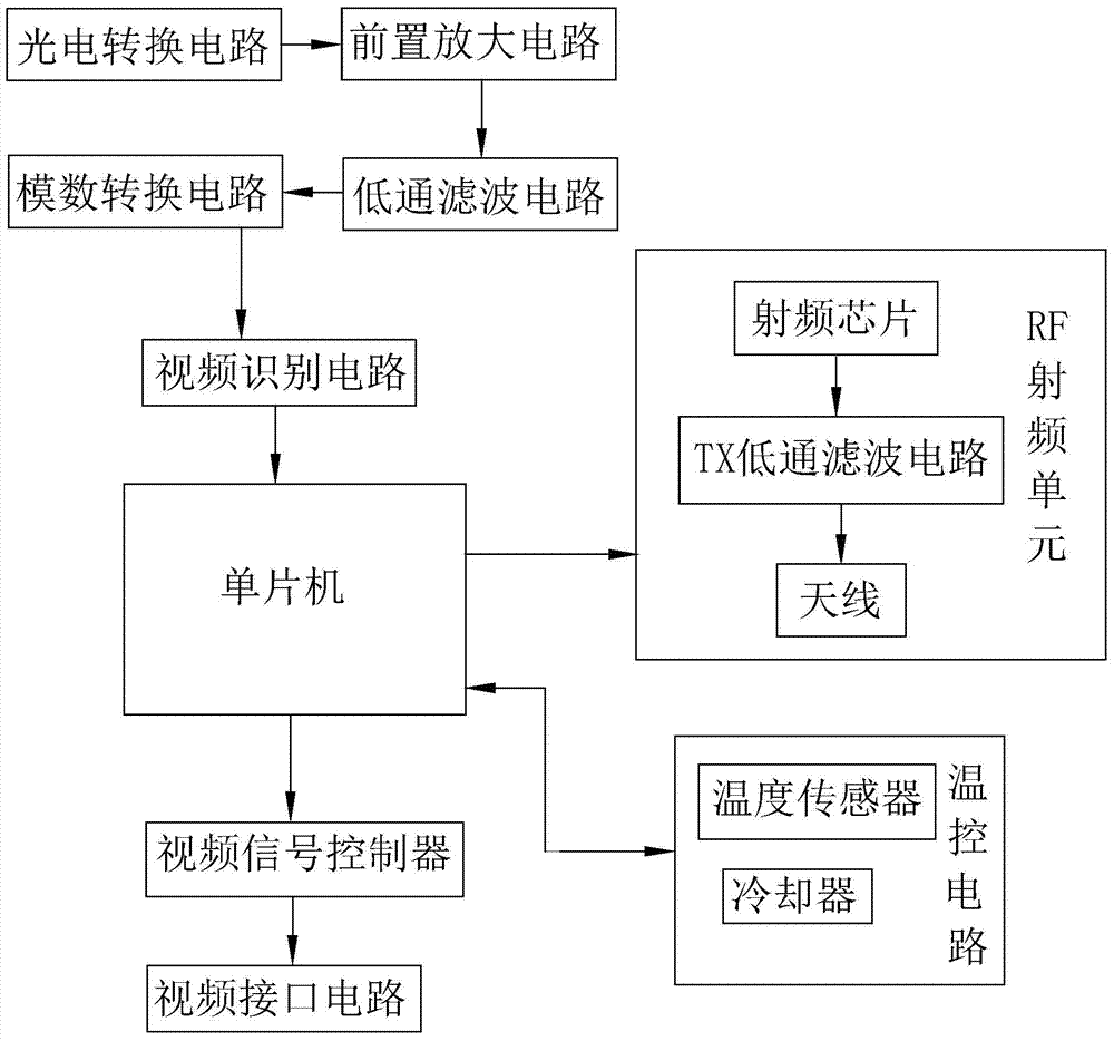
[0012] Such as figure 1 As shown, it is a structural block diagram of an optical power meter of the present invention, including a photoelectric conversion circuit, a preamplifier circuit, a low-pass filter circuit, an analog-to-digital conversion circuit and a single-chip microcomputer connected in sequence, and a USB interface connected to the output end of the single-chip microcomputer The circuit also includes a radio frequency unit connected with the output end of the single chip microcomputer. The low-pass filter circuit is a notch elliptic function filter circuit. The radio frequency unit is an RF radio frequency unit, which includes a radio frequency chip, a TX low-pass filter circuit and an antenna. One end of the TX filter circuit is connected to the TX pin of the radio frequency chip, and the other end is connected to the antenna. The optical signal is converted into a corresponding current signal through a photoelectric conversion circuit, and the corresponding cu...


PUM


Abstract

The invention discloses an optical power meter; the optical power meter comprises sequentially connected photoelectric conversion circuit, prepositive amplification circuit, low-pass filter circuit, analog-digital conversion circuit, and single-chip machine, as well as a USB interface circuit which is connected with an output terminal of the single-chip machine; the optical power meter further comprises a radio frequency unit which is connected with an output terminal of the single-chip machine; the radio frequency unit is a RF radio frequency unit which comprises a radio frequency chip, a TX low-pass filter circuit and an antenna; one end of the TX filter circuit is connected with TX pins of the radio frequency chip, and the other end is connected with the antenna. The optical power meter uses the RF radio frequency unit to achieve wireless transmission of measurement values of the optical power meter, thus the usual detection work is more convenient, and the work efficiency is increased; additionally, a temperature control circuit is able to timely cool down each module, thereby avoiding measurement errors caused by excessively high temperature, thus increasing the precision of the measurement.

Description

technical field [0001] The invention relates to the field of optical communication measurement, in particular to an optical power meter. Background technique [0002] With the rapid development of optical fiber communication technology, optical fiber testing equipment has also been continuously developed. A reliable, high-precision, and convenient output measuring instrument is particularly important for the detection and measurement of optical fiber transmission light. Optical power meter (optical power meter) is an instrument used to measure the absolute optical power or the relative loss of optical power passing through a section of optical fiber. It can be used in trunk line laying and equipment maintenance in communication engineering to determine the attenuation and loss of optical signal transmission. Existing optical power meters have the problem of a single output port, which cannot meet application requirements. For example, the Chinese invention patent applicatio...

Claims


Application Information

Patent Timeline
Patent Type & Authority Applications(China)
IPC IPC(8): G01J1/44G08C17/02G01J1/02
Inventor 江明珠徐庆富李清卉
Owner 广西铭瑶科技有限公司
Why Eureka
Try Eureka