Bidirectional current detection circuit

A detection circuit, bidirectional current technology, applied in the direction of current indication, voltage polarity indication, etc., can solve the problem of increasing circuit cost and complexity, not having the ability to accept voltages of positive and negative polarities, reducing sampling accuracy, etc. question

Active Publication Date: 2015-04-08
EAST GRP CO LTD
View PDF8 Cites 10 Cited by
  • Summary
  • Abstract
  • Description
  • Claims
  • Application Information

AI Technical Summary

Problems solved by technology

The current needs to be sampled in the energy conversion control. Since the direction of electric energy transmission is different, the direction of the current will be different. The selected current detection device must be able to detect both positive current and negative current, and can also convert the sampled current signal into a voltage. signal, the curren

Method used


Image

  • Bidirectional current detection circuit

Examples


Embodiment Construction

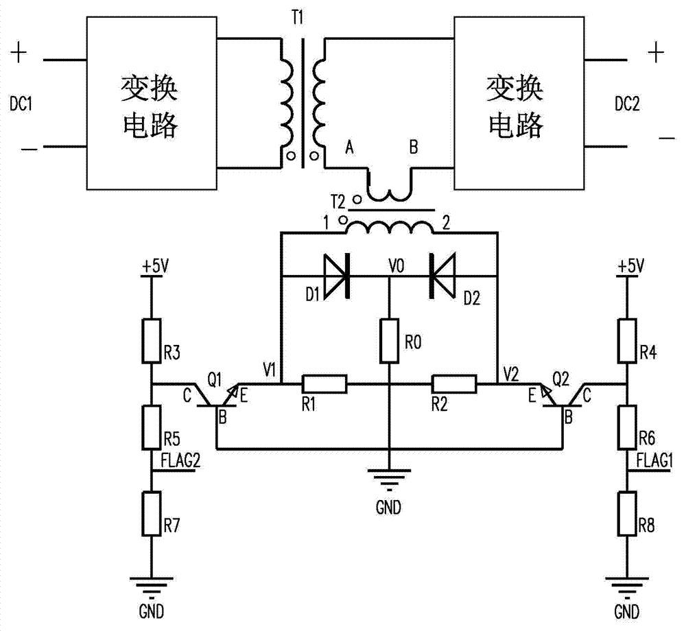
[0015] Such as figure 1 : The part above the current sensor T2 is a bidirectional DC converter, which has two ports DC1 and DC2; in the output side circuit of the current sensor T2, the diode D1 belongs to the first unidirectional conduction branch, and the diode D2 belongs to the second one One-way conduction branch, the two one-way conduction branches share the sampling resistor R0; the part to the left of potential point V1 and the part to the right of potential point V2 is the direction to identify the voltage conversion circuit, and its identification terminals FLAG1 and FLAG2 respectively output the control chip circuit available input voltage. The bidirectional current detection circuit given in this embodiment is suitable for a control chip circuit that accepts a positive voltage input.

[0016] When the energy is transferred from DC1 to DC2, the input current direction of current sensor T2 is from pin B to pin A, then the output current of current sensor T2 flows out...


PUM


Abstract

The invention provides a bidirectional current detection circuit. The bidirectional current detection circuit is that a circuit at the output side of a current inductor is characterized in that a first pin (1) of the output end of a current inductor T2 is sequentially connected to a second pin (2) through a divider resistor R1 and a divider resistor R2; two one-way connection branches with sampling resistors are provided; the first one-way connection branch is connected in parallel with the divider resistor R1, and while the second one-way connection branch is connected in parallel with the divider resistor R2; the two one-way connection branches are in opposite connection ways; the potentials of potential points (V1, V2) in the circuit at the output side of the current inductor T2 change as the output current direction of the current inductor T2 changes; the potentials of the potential points (V1, V2) are converted into voltage which can be input through a control chip circuit by a direction recognizing voltage conversion circuit, and thus the current direction of the control chip circuit can be recognized without modulating; sampling voltage of sampling resistors in the two one-way connection branches is output with the same polarity through a sampling voltage output circuit and then the control chip circuit can detect the current.

Description

technical field [0001] The invention relates to a bidirectional current detection circuit. Background technique [0002] Bidirectional power converters can realize bidirectional transfer of energy, and are widely used in UPS power supplies, electric vehicles and other fields. The current needs to be sampled in the energy conversion control. Since the direction of electric energy transmission is different, the direction of the current will be different. The selected current detection device must be able to detect both positive current and negative current, and can also convert the sampled current signal into a voltage. signal, the current detection device is required to detect both positive voltage and negative voltage, but most control chips generally do not have the ability to accept positive and negative voltages, so a conditioning circuit is required to shift the voltage. This increases the cost and complexity of the circuit on the one hand, and reduces the sampling accu...

Claims


Application Information

Patent Timeline
IPC IPC(8): G01R19/14
Inventor 陈书生
Owner EAST GRP CO LTD
Why Eureka
Try Eureka