Ergonomic dynamic design method based on chaotic recognition

A technology of dynamic design and ergonomics, applied in the direction of instruments, self-adaptive control, control/regulation systems, etc., can solve the problems of drivers and operators such as psychological irritability, inability to use vibration, and easy occurrence of serious occupational diseases, so as to reduce personal injuries , Eliminate nonlinear vibration chaotic state response, reduce the effect of mental fatigue

Inactive Publication Date: 2015-04-08
FUJIAN CHUANZHENG COMM COLLEGE
5 Cites 4 Cited by

AI-Extracted Technical Summary

Problems solved by technology

[0003] (1) Static design only considers static analysis, which is too simple to be suitable for applications in vibration utilization engineering, construction machinery vibration and other fields
[0004] (2) The simple dynamic design only considers the impact of mechanism or environmental vibration on the structural damage of the machinery (machine) itself, and seldom considers the i...

Abstract

The invention belongs to the field of engineering machinery, and particularly relates to an ergonomic dynamic design method based on chaotic recognition. The method adopting the technical scheme can be used in the fields of the design of various kinds of machinery with the ergonomic design requirements, such as road roller. According to the technical scheme, on the basis of building a dynamic model, the aspects such as the weight of a mechanical equipment machine frame structure to be designed, the rigidity coefficient of a mechanical vibration reducing system and the damping coefficient are subjected to dynamic design through avoiding the chaotic state response due to non-linear vibration of the machine frame system, further, from the driving comfort aspect of a driver in the ergonomics, the non-linear chaotic vibration phenomenon of the system is avoided under the condition that the whole machine of mechanical equipment meets the movable and static loads, the driving comfort is improved, and the service life of each mechanical equipment vibration structural element is prolonged.

Application Domain

Technology Topic

Image

  • Ergonomic dynamic design method based on chaotic recognition
  • Ergonomic dynamic design method based on chaotic recognition
  • Ergonomic dynamic design method based on chaotic recognition

Examples

  • Experimental program(1)

Example Embodiment

[0047] In order to facilitate the understanding of the technical solution of the present invention, the present invention will be further described in detail below in conjunction with the following examples, but the implementation of the present invention is not limited thereto. Any equivalent implementation that does not deviate from the basic concept of the present invention belongs to the protection of the present invention. range.
[0048] Here, taking the ergonomic dynamic design of a road roller as an example, the implementation process of the ergonomic dynamic design method based on chaos recognition of the present invention will be specifically described.
[0049] According to the structure principle of the roller, a dynamic model is established.
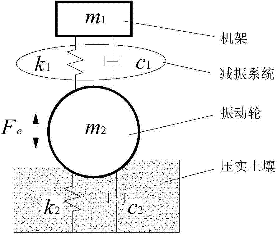
[0050] figure 1 It is a two-degree-of-freedom dynamic model diagram for the ergonomic dynamic design of a roller.
[0051] The vibratory roller can be simplified to figure 1 The two-degree-of-freedom dynamic model shown, where m 1 , M 2 Is the mass of the frame and vibrating wheel, k 1 , C 1 Is the stiffness coefficient and damping coefficient of the frame damping system, k 2 , C 2 Is the stiffness coefficient and damping coefficient of the compacted material, F e Is the vibration excitation force, by formula F e =F sin(ωt) is determined, where F excitation force amplitude, ω is the vibration angular frequency.
[0052] The kinetic equation is established as follows:
[0053] m 1 x · · 1 + c 1 ( x · 1 - x · 2 ) + k 1 ( x 1 - x 2 ) = m 1 g m 2 x · · 2 + g ( t ) - c 1 ( x · 1 - x · 2 ) - k 1 ( x 1 - x 2 ) = F e ( t ) + m 2 g - - - ( 1 )
[0054] Where x 1 , Is the displacement, velocity and acceleration response of the frame vibration (the direction is positive downward), x 2 , Is the displacement, velocity and acceleration response of the vibrating wheel vibration (the direction is positive), g is the acceleration of gravity, generally 9.8m/s 2 , G(t) is the reaction force of compacted soil material, which can be divided into two situations: jumping off the ground and touching the ground:
[0055] g ( t ) = 0 x 2 0 c 2 x · 2 + k 2 x 2 x 2 ≥ - - - ( 2 )
[0056] figure 1 All parameters m 1 , M 2 , K 1 , C 1 , K 2 , C 2 , F e In, first determine the mass of vibrating wheel m according to the tonnage of the roller to be designed and produced 2 =3000kg and excitation force amplitude F=82kN and excitation frequency 35Hz, from ω=2π×35 and F e (t)=F sin(ωt) can determine F e (t); Secondly, the representative stiffness coefficient and damping coefficient of the asphalt compacted soil material are used to determine k 2 =11MN/m and c 2 =9kNs/m; then pre-select the stiffness coefficient and damping coefficient k of the vibration reduction system by referring to the conventional roller design manual 1 =1.7×10 5 N/m and c 1 =4.3kNs/m. At this moment figure 1 All parameters m 1 , M 2 , K 1 , C 1 , K 2 , C 2 , F e Only the rack mass is left in m 1 Is an unknown quantity, that is, the first design goal, introducing the rack quality factor as m 1 /m 2 , When setting a quality factor m 1 /m 2 When the value (for example, 1), the time history image of the vibration speed of the rack can be obtained by applying Equation 1 and Equation 2 (because this method is more conventional, it is omitted here), and then taking the points according to the period (bifurcation diagram method) can obtain the Quality factor m 1 /m 2 Corresponding to the nonlinear characteristics of the vibration speed response of the frame figure 2 The abscissa is m 1 /m 2 =1 column of data points), and so on to select a series of quality coefficient m 1 /m 2 When you can get figure 2 The chaotic identification bifurcation diagram of the frame speed of the vibration system is shown by figure 2 It can be seen that the rack quality factor m 1 /m 2 It is reasonable to design according to the range of 0.8~1, which can avoid the chaotic vibration zone of the frame well, thereby improving the driving comfort of the driver, and preventing the roller fasteners from being loosened and failed early due to the disorderly vibration and impact. .
[0057] in figure 2 Quality factor m 1 /m 2 In the range of 0.8~1, the optimal quality coefficient m can be determined according to the minimum chaotic value 1 /m 2 =0.9, so the first design target rack mass m 1 Is determined, that is, m 1 = 2700kg.
[0058] As a further improvement, the next design goal is the stiffness coefficient k of the frame damping system 1 , Because the parameters of the existing roller conventional design manual are derived from static design or simple dynamic design theory, it needs to be further improved. The stiffness coefficient k of the vibration reduction system is pre-selected in the previous step 1 =1.7×10 5 N/m should be corrected. At this moment figure 1 All parameters m 1 , M 2 , K 1 , C 1 , K 2 , C 2 , F e Only k 1 Is an unknown quantity, which is the second design goal, due to the stiffness coefficient k of the damping system 1 Affect the natural vibration frequency ω of the frame, so the parameter is introduced In the same way, a series of bifurcation diagrams of the frame speed chaos identification of the vibration system with natural frequency ω are obtained, as image 3 As shown, a reasonable range of the natural frequency ω of the rack is 3~9.5 (chaos identification analysis is the same as m 1 Of the determination steps), thus by image 3 According to the minimum chaotic value, the optimal natural frequency of the rack ω=8.5 can be determined. The second design target frame damping system stiffness coefficient design recommended value k is obtained 1 =1.95×10 5 N/m.
[0059] As a further improvement:
[0060] Design stiffness coefficient k of frame damping system 1 =1.95×10 5 After N/m is determined, the next third design goal is the damping coefficient c of the frame damping system 1 In the same way, the parameters obtained from the existing roller conventional design manual need to be further improved. The damping coefficient c of the vibration reduction system pre-selected in the previous step 1 = 4.3kNs/m should be corrected. At this moment figure 1 All parameters m 1 , M 2 , K 1 , C 1 , K 2 , C 2 , F e Only c 1 Is an unknown quantity, which is the third design goal, the introduction of damping ratio (ζ affects the energy dissipation of the system). Similarly, a series of damping ratio coefficient ζ vibration system frame speed chaotic identification bifurcation diagrams are obtained, such as Figure 4 As shown, the reasonable damping ratio coefficient ζ range is 0.17~0.23 (chaotic identification analysis is the same as m 1 The determination process of ), therefore, the best damping ratio coefficient ζ=0.205 can be determined according to the minimum chaotic value. Then the design recommended value c of the damping coefficient of the third design target frame damping system can be obtained 1 =4.7kNs/m.
[0061] This written description uses examples to disclose the invention, including the best mode, and also enables those skilled in the art to make and use the invention. The patentable scope of the present invention is defined by the claims, and may include other examples that occur to those skilled in the art. If such other examples have structural elements that are not different from the literal language of the claims, or if such other examples include equivalent structural elements that are not substantially different from the literal language of the claims, then such other examples are intended to be Within the scope of the claims. To the extent that it will not cause inconsistency, all citations referred to in this article are incorporated into this article by reference.

PUM

no PUM

Description & Claims & Application Information

We can also present the details of the Description, Claims and Application information to help users get a comprehensive understanding of the technical details of the patent, such as background art, summary of invention, brief description of drawings, description of embodiments, and other original content. On the other hand, users can also determine the specific scope of protection of the technology through the list of claims; as well as understand the changes in the life cycle of the technology with the presentation of the patent timeline. Login to view more.

Similar technology patents

Bank security device

InactiveCN102852116AAvoid safety accidentsReduce personal injuryMarine site engineeringEngineeringSecurity guarantee
Owner:WUXI LAIJITE INFORMATION TECH

Auxiliary component and method for installing grounding wire of transmission line

ActiveCN109586130AEasy installationReduce personal injuryClip conductor connectionMulticonductor cable end piecesTransmission lineGround line
Owner:ZAOZHUANG POWER SUPPLY COMPANY OF STATE GRID SHANDONG ELECTRIC POWER +1

Classification and recommendation of technical efficacy words

  • Reduce personal injury

Elevator pit accumulated water automatic pumping and security control method and device

InactiveCN104961016AReduce damage and rustReduce personal injuryPump controlElevatorsAutomatic processingControl switch
Owner:贵州航奥电气有限公司

Method of radio alarm

ActiveCN102693604AIncrease chance of escapeReduce personal injuryBroadcast specific applicationsAlarmsVIT signalsReal-time computing
Owner:CHINA ACAD OF SAFETY SCI & TECH

Sand blasting control system

Owner:CHANGCHUN INST OF APPLIED CHEMISTRY - CHINESE ACAD OF SCI

Miter clamping system

ActiveUS20210039228A1Reduce material damageReduce personal injuryWork holdersClampsKnuckleEngineering
Owner:STOUFFER RODNEY SCOTT

Lifesaving device used for passenger car fallen into water

ActiveCN110588560ALow survival rateReduce personal injuryPedestrian/occupant safety arrangementFall into waterAutomotive engineering
Owner:ANHUI ANKAI AUTOMOBILE
Why Eureka
Try Eureka