Method for modulating space vectors of double inverters

A technology of space vector modulation and dual inverters, applied in vector control systems, control systems, control generators, etc., can solve the problem of low DC bus voltage utilization, improve voltage utilization, increase output voltage, reduce The effect of switching frequency

Inactive Publication Date: 2015-04-08
HARBIN INST OF TECH
View PDF2 Cites 32 Cited by
  • Summary
  • Abstract
  • Description
  • Claims
  • Application Information

AI Technical Summary

Problems solved by technology

[0003] The purpose of the present invention is to solve the problem that the existing basic space voltage vector that does not generate common mode voltage is selected to modulate the voltage, and the utilization rate of the DC bus voltage is low, and a space vector modulation method for dual inverters is provided.

Method used


Image

  • Method for modulating space vectors of double inverters
  • Method for modulating space vectors of double inverters
  • Method for modulating space vectors of double inverters

Examples


specific Embodiment approach 1

[0021] Specific implementation mode one: the following combination Figure 12 Describe this embodiment, a space vector modulation method for dual inverters described in this embodiment, the method is as follows: first divide the space voltage vector plane into six sectors, and decompose the reference voltage vector into two segments of vectors: One of the vectors is equivalent to clamping one of the dual inverters in a specific switch state; the other vector is modulated by another inverter in its six sub-sectors; within the maximum voltage range Modulation is performed to introduce an equivalent zero-vector distribution factor during vector synthesis, and the common-mode voltage generated by the zero-vector is used to offset the common-mode voltage generated during basic voltage-vector synthesis to suppress the common-mode voltage of the dual inverters.

[0022] This method is realized by DSP, and this method comprises the following steps:

[0023] Step 1. Calculate the αβ-a...

specific Embodiment approach 2

[0037] Specific implementation mode two: the following combination Figure 1 to Figure 11 Specific embodiments of the present invention will be described.

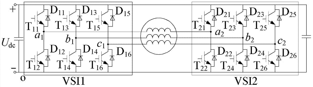
[0038] figure 1 In order to isolate the bus dual inverter system topology diagram, the dual inverter consists of two two-level inverters VSI1 and VSI2, the two inverters are respectively connected to the two ends of the open winding motor winding, and the two inverters The DC bus of the device is connected together.

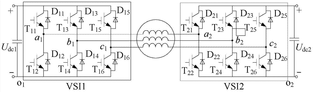
[0039] figure 2 It is the topology diagram of the dual-inverter system with common bus. The dual-inverter is composed of two two-level inverters VSI1 and VSI2. The two inverters are respectively connected to the two ends of the open-winding motor winding. The DC buses of the controllers are isolated from each other and powered by two independent DC power supplies.

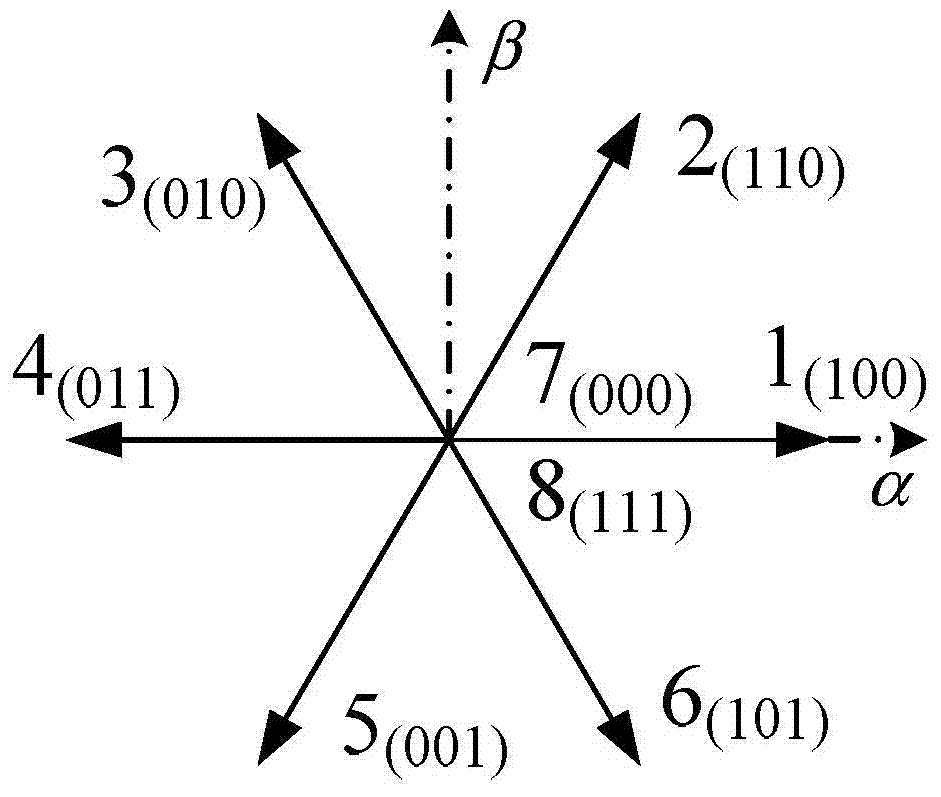
[0040] image 3 It is the spatial distribution diagram of the voltage vectors output by the inverter VSI1 in the dual inverter. VSI1 has 8 vo...


PUM


Abstract

The invention discloses a method for modulating space vectors of double inverters, and belongs to the field of inverter control. The method is used for solving the problem that in the prior art, when basic space voltage vectors which do not generate common-mode voltage are selected to modulate voltage, the utilization of direct-current bus voltage is low. The method comprises the steps that a space voltage vector plane is divided into six sectors, a reference voltage vector is divided into two vectors, one vector is equivalent to the operation that one of the double inverters is clamped in a specific switching state, and the other vector is modulated by the other inverter in six sub-sectors of the inverter to be achieved; modulation is conducted within the maximum voltage range, an equivalent zero vector distribution factor is introduced when the vectors are synthesized, the common-mode voltage generated in the process of synthesis of the basic voltage vectors is counteracted with common-mode voltage generated by a zero vector, and common-mode voltage of the double inverters is restrained.

Description

technical field [0001] The invention relates to a SVPWM (short for Space Vector Pulse Width Modulation, Space Vector Pulse Width Modulation) method, which belongs to the field of inverter control. Background technique [0002] The neutral point of the traditional three-phase motor winding is separated, and two inverters are used to supply power from both ends of the winding respectively, forming an open winding motor drive system powered by dual inverters. The voltage vector distribution of the dual inverter output is the same as that of the three-level inverter, which is a new type of multi-level topology, such as figure 1 and figure 2 shown. Compared with the traditional clamped three-level inverter, the double inverter does not have the problem of capacitor voltage balance, and the open winding motor system powered by the double inverter has the advantages of high flexibility in current control and superior fault tolerance performance. The DC terminals of the two inve...

Claims


Application Information

Patent Timeline
Patent Type & Authority Applications(China)
IPC IPC(8): H02M7/5387H02P21/14H02P27/12
CPCH02P27/12
Inventor 安群涛孙东阳段建东孙立志孙力
Owner HARBIN INST OF TECH
Why Eureka
Try Eureka