
Self-propelled floor cleaning machine and a filter system module

A system module and cleaning machine technology, applied in cleaning machinery, manual floor scrubbing machinery, cleaning equipment, etc., can solve the problem of filter efficiency decline and achieve the effect of optimizing the suction channel guidance

Inactive Publication Date: 2015-04-08
ALFRED KARCHER GMBH & CO KG
View PDF7 Cites 1 Cited by
  • Summary
  • Abstract
  • Description
  • Claims
  • Application Information

AI Technical Summary

Problems solved by technology

Filters become less efficient over time and must therefore be purged after a period of time

Method used


Image

  • Self-propelled floor cleaning machine and a filter system module
  • Self-propelled floor cleaning machine and a filter system module
  • Self-propelled floor cleaning machine and a filter system module

Examples


Embodiment Construction

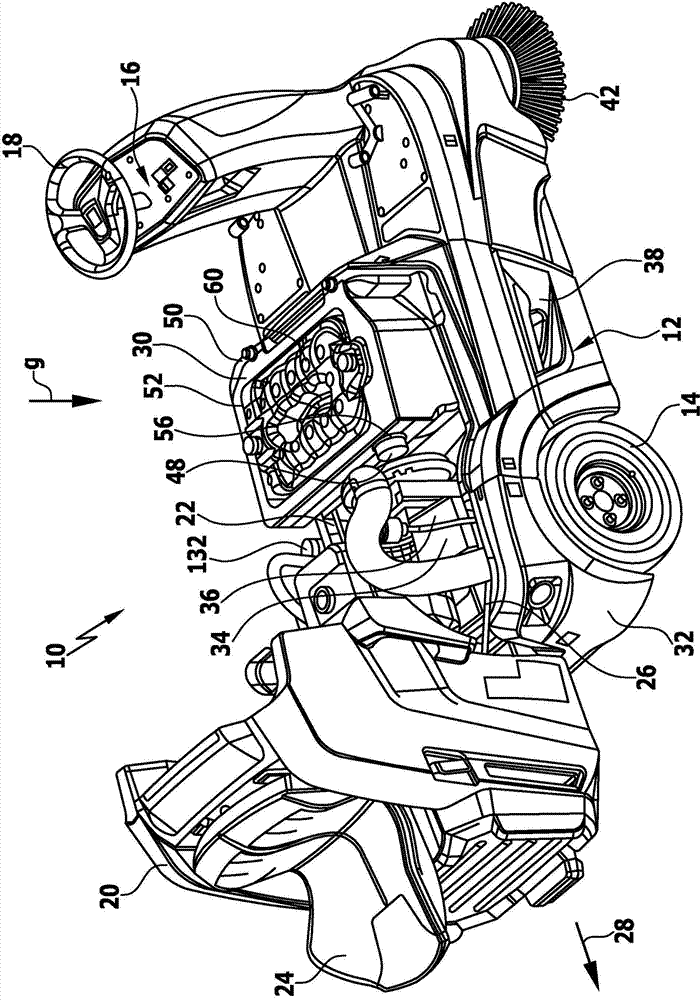
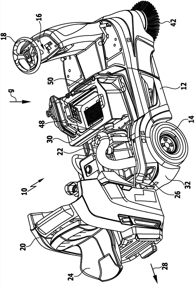
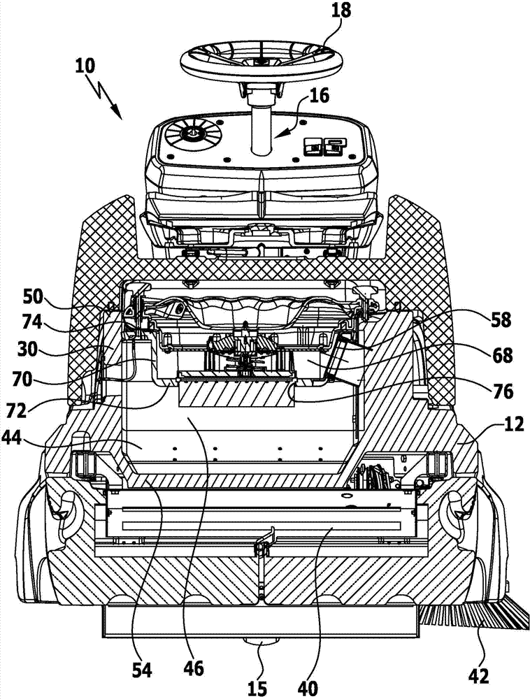
[0054] An embodiment of the self-propelled floor-cleaning machine according to the invention is a sweeper, which is Figure 1 to Figure 3 is shown as a whole and is here denoted by 10 . The sweeper 10 has a chassis 12 . A rear wheel arrangement 14 and a front wheel arrangement 15 are arranged on the chassis 12 . The front wheel arrangement 15 includes one or more front wheels. One or more front wheels can be steered by a steering device 16 with a steering wheel 18 .

[0055] A cover 20 (housing cover) is arranged on the chassis 12 and covers the motor compartment 22 .

[0056] A driver's seat 24 is arranged on the cover 20 .

[0057] In an embodiment, the cover 20 is pivotally retained on the chassis 12 . A corresponding articulation device 26 is arranged in the region of the rear wheel arrangement 14 . Via this hinge, the cover 20 can be lifted in direction 28 in order to gain access to the motor compartment 22 . Furthermore, access to the receptacle 30 for the filter ...


PUM


Abstract

The invention relates to a self-propelled floor cleaning machine (10), comprising a chassis (12), a suction fan arrangement (36) and a filter arrangement which is connected upstream of the suction fan arrangement (36) in an air flow path; wherein a receiving arrangement (30) for at least one filter system module (60 / 160) is disposed on the chassis (12), wherein the at least one filter system module (60 / 160) is or can be fixed as a whole unit on the receiving arrangement (30), and wherein the at least one filter system module (60 / 160) comprises at least one pressure vessel (62), a filter cleaning arrangement (148), at least one filter (78 / 162a; 162b) and one or more connections (124, 130, 134).

Description

technical field [0001] The invention relates to a self-propelled floor-cleaning machine, in particular a sweeping machine, comprising a chassis, a blower unit and a filter unit, the filter unit being connected in front of the air flow path of the blower unit. [0002] Furthermore, the invention also relates to a filter system module. Background technique [0003] In the unpublished international patent application PCT / EP2011 / 051656 of February 4, 2011 by the same applicant, a sweeping machine is described having sweeping brushes and objects to be swept which can be driven in rotation container, and a suction fan for sucking dust-laden air through the suction channel and the suction shaft with sweeping brushes in the direction of flow, and at least one filter for separating dust from the sucked air, wherein at least one filter is for The purge can be acted on the clean side via at least one ambient air valve with ambient air stored under pressure in the pressure vessel. The...

Claims


Application Information

Patent Timeline
Patent Type & Authority Applications(China)
IPC IPC(8): E01H1/08A47L11/24A47L11/30A47L11/40
CPCA47L11/4027A47L11/30A47L11/24E01H1/0845A47L11/4033
Inventor 弗洛里安·阿布特巴斯蒂安·杜麦利安德烈亚斯·克拉尔
Owner ALFRED KARCHER GMBH & CO KG
Learn More