
Ignition system

一种点火系统、次级绕组的技术,应用在点火系统领域

Inactive Publication Date: 2015-04-08
DELPHI INT OPERATIONS LUXEMBOURG S A R L
View PDF6 Cites 6 Cited by
  • Summary
  • Abstract
  • Description
  • Claims
  • Application Information

AI Technical Summary

Problems solved by technology

However, a real problem with this system is the alternating polarity of the current in the secondary winding, which prevents the use of diodes in the line leading from the secondary winding terminals to the spark plug

Method used


Image

  • Ignition system
  • Ignition system
  • Ignition system

Examples


Embodiment Construction

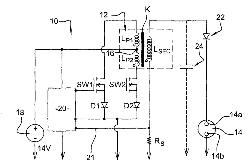
[0037] refer to figure 1 , a preferred embodiment of the present ignition system 10 is shown in an electrical schematic diagram comprising a dual primary winding ignition transformer 12 or ignition coil acting on a set of spaced electrodes 14a and 14b in a spark plug 14 such as may be connected to an internal combustion engine One combustion cylinder is associated (not shown).

[0038] In addition to the two primary windings denoted LP1 and LP2, the ignition coil 12 also includes a secondary winding LSEC and a common magnetic coupling K1; these three windings are magnetically coupled.

[0039] The system 10 is configured such that both ends of the first and second primary windings LP1, LP2 can be switched to a common ground, such as the chassis ground of a car, in an alternating manner by switches SW1, SW2. Switches SW1 and SW2 may both be in the form of IGBTs (Insulated Gate Bipolar Transistors) or other suitable semiconductor switching devices.

[0040]Preferably, the turn...


PUM


Abstract

An ignition system for an internal combustion engine comprises an ignition transformer with two primary windings (L P1 , L P2 ). The ignition system is designed to generate, for a given ignition event, a unipolar current (I SEC ) through the secondary winding (L SEC ) by way of a control circuit (20) that is configured to first energize and deenergize the first primary winding (L P1 ) to establish a first electrical arc across the spark-plug electrodes (14) and, when the current (I SEC ) in the secondary winding reaches, or drops below, a current threshold (I SEC_TH ), repeatedly energizes and deenergizes the second primary winding (L P2 ) to establish a plurality of second current pulses across the electrodes in order to maintain the burn phase.

Description

technical field [0001] The present invention relates generally to ignition systems for internal combustion engines, and more particularly to ignition systems including an ignition transformer having two primary windings. Background technique [0002] As is well known, the combustion of gasoline in a reciprocating engine requires a flame starting device, commonly referred to as an ignition system. The ignition system consists of two main components: [0003] spark plugs; and [0004] ignition coil or transformer. [0005] The spark plug represents a direct interface via its ignition face to the center of its own flame and an independent electrical feedthrough into the combustion chamber. The task of the ignition transformer is to provide the right form of energy to start combustion. This is usually divided into two consecutive and distinct phases. [0006] The first stage stores electrical energy in the transformer's inductor, and the next stage releases the previously s...

Claims


Application Information

Patent Timeline
Patent Type & Authority Applications(China)
IPC IPC(8): F02P9/00F02P3/055F02P15/08F02P15/10F02P3/04
CPCF02P3/0407F02P3/0442F02P3/055F02P9/007F02P2017/121F02P15/10F02P15/12F02P9/002
Inventor V·海泽M·勒纳茨F·洛伦茨
Owner DELPHI INT OPERATIONS LUXEMBOURG S A R L
Learn More