
Industrial robot

A technology of industrial robots and robots, applied in the directions of manipulators, manufacturing tools, claw arms, etc., can solve the problems of larger cable guiding space and worse appearance, and achieve the effect of less retention and less damage

Active Publication Date: 2015-04-15
NACHI-FUJIKOSHI
View PDF9 Cites 9 Cited by
  • Summary
  • Abstract
  • Description
  • Claims
  • Application Information

AI Technical Summary

Problems solved by technology

[0003] However, in the structure where the cables are guided to the outside of the robot, the cable guide space around the robot becomes large
In addition, the appearance also deteriorates

Method used


Image

  • Industrial robot
  • Industrial robot
  • Industrial robot

Examples


Embodiment Construction

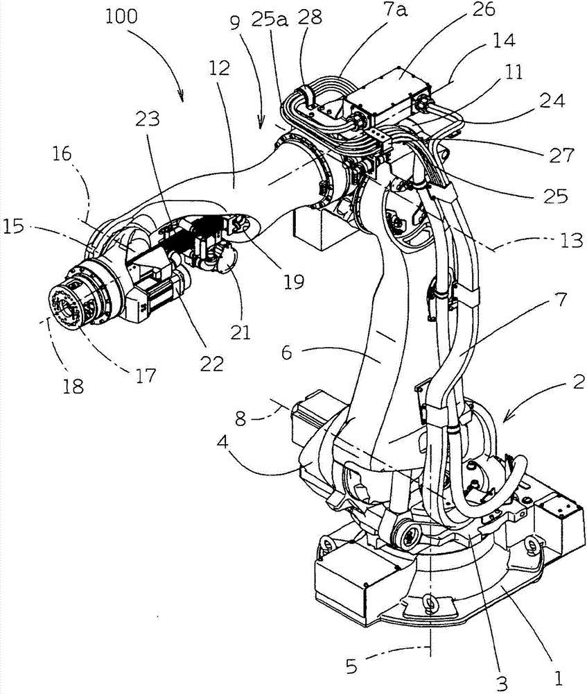
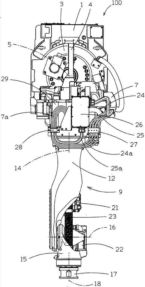
[0030] Next, embodiments of the present invention will be described with reference to the drawings. First, an overall configuration of an industrial robot 100 (welding robot) showing an embodiment of the present invention will be described. like figure 1 and figure 2 As shown, for example, a rack 2 is placed on a base 1 installed on an installation surface such as a floor surface. The frame 2 has a base plate 3 arranged on the upper surface of the base 1 , and a stand plate 4 standing up from the base plate 3 . In addition, a motor (not shown) for rotating the entire rack 2 in a horizontal plane (in a plane parallel to the floor surface) is attached to the upper surface of the base plate portion 3 .

[0031] By rotating the motor shaft of the motor in a predetermined direction, the frame 2 rotates around the first rotation axis 5 provided perpendicular to the floor surface.

[0032] The lower end portion of the lower arm 6 is mounted on the vertical plate portion 4 of th...


PUM


Abstract

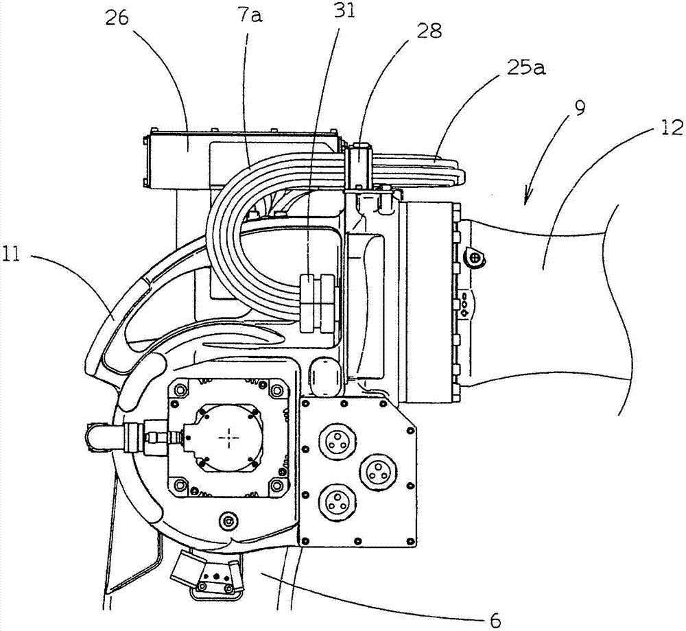
The invention provides an industrial robot. Cables go through an arm equipped with a wrist and arranged on one side of the industrial robot, so that an unfavorable condition that cables are scattered along with movement of the robot is avoided. An opening part (11a) which allows a cable (7a) to go through is disposed in one end side (11) of a hollow part (12). One end side of the cables (7a) is connected with relay parts (26, 27) on the base of the arm. The cables are provided with a bending part (7a) which bends between the relay parts and the opening part, a restraint member (31) which restrains the cable (7a) of the bending part, and the other end part (7b) which goes through the hollow part towards the wrist (15). The restraint member is larger than the opening of the opening part and can be pressed against the opening part or movably separated from the opening part. The length from the restraint member to the other end part is longer than the necessary length of the cable needed for the motion of the wrist. The restraint member can be detached and assembled in the way of clamping the cable. A guiding member (29) which guides the restraint member is provided so as to allow the central axes of the restraint member and the opening part to be consistent.

Description

technical field [0001] The present invention relates to an industrial robot in which a cable is provided in an arm, one end of which is rotatably attached to a robot main body, and a rotatably wrist is attached to the other end. Background technique [0002] A general industrial robot (hereinafter simply referred to as "robot") has: a robot main body; an arm that can be rotatably installed relative to the robot main body; end effector. The power cord for supplying power to the driving means (for example, servo motor) for rotating the arm and the wrist, and the air tube for supplying air to the air cylinder attached to the end effector are gathered together in one harness (hereinafter this state The components of the robot are called "cables"), and are housed inside the robot body or guided by being fixed on the outer surface. [0003] However, in the structure where the cables are guided to the outside of the robot, the cable guide space around the robot becomes large. In...

Claims


Application Information

Patent Timeline
IPC IPC(8): B25J18/00B25J19/00
Inventor 伊东辉树高田昌幸七泽幸二
Owner NACHI-FUJIKOSHI
Learn More