End wall structure of railway vehicle and processing method of end wall structure

A rail vehicle and processing method technology, applied to the railway car body, railway car body parts, transportation and packaging, etc., can solve the problem of limited impact speed, etc., and achieve the effects of improving impact resistance, ensuring safety, and saving manufacturing costs

Active Publication Date: 2015-04-15
CRRC QINGDAO SIFANG CO LTD
View PDF6 Cites 10 Cited by
  • Summary
  • Abstract
  • Description
  • Claims
  • Application Information

AI Technical Summary

Problems solved by technology

The end wall of this structure is a closed frame structure formed by the connection between the door column, the top curved beam, the end corner column and the connecting plate, which improves the strength and rigidity of the end wall and increases the resistance to impact, but it only has a rigid structure , can only transmit the impact energy to the car body frame behind, and there are no parts that can absorb energy, and the impact speed it can withstand is limited

Method used


Image

  • End wall structure of railway vehicle and processing method of end wall structure
  • End wall structure of railway vehicle and processing method of end wall structure
  • End wall structure of railway vehicle and processing method of end wall structure

Examples


Embodiment 1

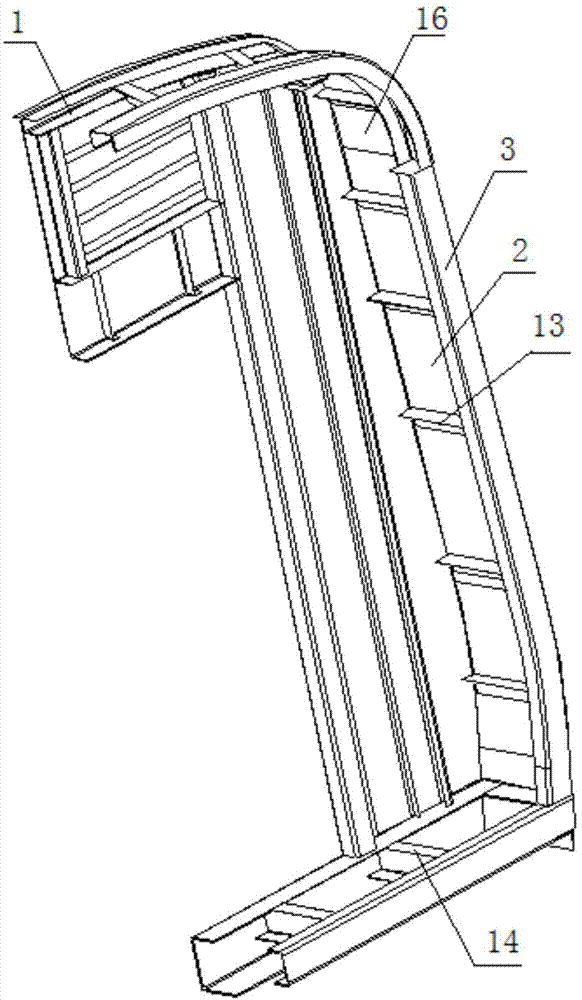
[0040] Such as figure 1 As shown, an end wall structure of a rail vehicle includes a front end wall 1, an energy absorbing component 2, and a rear end frame 3, and the front end wall 1 and the rear end frame 3 are fixedly connected to the energy absorbing component 2 on both sides of the energy absorbing component 2 .

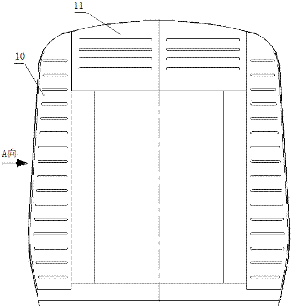
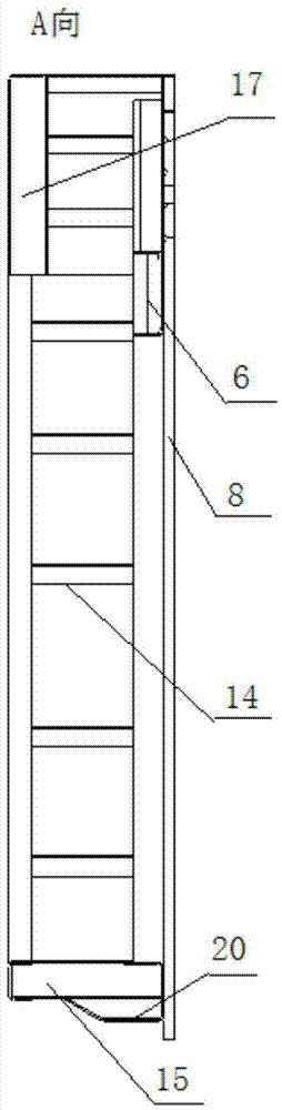
[0041] Such as figure 2 and Figure 5 As shown, the front wall 1 includes the door column 4, the end corner column 5, the door beam 6, the end top curved beam 7, the end wall panel 8, the buffer beam 9, the end top curved beam 7 and the top of the door column 4 and the end corner column 5 Fixedly connected, the two ends of the crossbeam 6 on the door are fixedly connected with the door columns 4 on both sides, and the buffer beam 9 is fixedly connected with the bottoms of the door columns 4 and the end corner columns 5, thus forming a closed front frame.

[0042] The end wall panel 8 is composed of an upper end wall panel 11 and a lower end wall panel 10, t...

Embodiment 2

[0074] The installation method of step b in the processing method of the end wall structure in the first embodiment is as follows:

[0075] First connect several skins 16 into a whole by arc welding or adopt a long skin, and then calculate and determine the position where the support needs to be positioned on the skin 16 and the connection position of the energy-absorbing component 2 and the side beam 20 with the skin 16 , and then the skin 16 is fixed into a roughly box-shaped structure by tooling equipment (not shown in the figure), the shape and size of the cross-section of the box-shaped structure are adapted to the cross-section of the rear end frame 3, and the skin 16 at the joint is passed through Arc welding connection, the bottom longitudinal beam 15 and the side beam 20 are connected by arc welding, and then each longitudinal beam and side beam 20 in the energy-absorbing part 2 are respectively connected with the skin 16 according to the predetermined position by resi...

Embodiment 3

[0078] The installation method of step b in the processing method of the end wall structure in the first embodiment is as follows:

[0079] Connect the bottom longitudinal beam 15 and the side beam 20 in the energy-absorbing component 2 by arc welding, connect each longitudinal beam and side beam 20 with the front frame and the rear end frame 3 by arc welding, and then connect the skin 16 with the longitudinal beam and The side beams 20 are connected by resistance spot welding, the longitudinal beams are arranged in parallel longitudinally, and then the two sides of the skin 16 and the front frame and the rear frame 3 are connected by resistance spot welding to form an end wall structure.

[0080] The processing methods and structures of other end wall structures are the same as those in Embodiment 1, and will not be repeated in this embodiment.

[0081] The end wall structure of this rail vehicle uses the modular theory to divide the end wall structure into three parts: the f...


PUM


Abstract

The invention relates to an end wall structure of a railway vehicle and a processing method of the end wall structure. The end wall structure comprises a front end wall; the front end wall comprises end door stand columns, end corner posts, a door top rail, an end roof camber beam and an end wall plate; the end wall structure also comprises an energy absorption component and a back end framework; the front end wall and the back end framework are fixedly connected with the energy absorption component at two sides of the energy absorption component. The processing method of the end wall structure comprises the steps of a, preassembling the end wall structure; b, fixing the end wall structure to the end of a vehicle body. The energy absorption component and the back end framework are additionally arranged on the end wall structure, the end wall structure can participate in deformation and absorb energy under the impact, the impact resistance performance of the end wall is improved, the safety of the passengers is guaranteed, a modular method is adopted, and the installation efficiency of the end wall structure is guaranteed.

Description

technical field [0001] The invention relates to an end wall structure of a rail vehicle and a processing method thereof, in particular to an end wall structure capable of deforming and absorbing impact energy when subjected to an impact and a processing method thereof. Background technique [0002] With the rapid popularization of domestic urban rail transit and the substantial increase in vehicle speed, people have put forward higher requirements for the safety of rail vehicles. At present, the end wall and the car body of rail vehicles are mostly welded structures, and neither the end wall nor the car body is equipped with energy-absorbing components. After a collision, all energy is absorbed by the coupler buffer. The device cannot completely absorb the impact energy, and the remaining energy will cause the vehicle to collide and deform, affecting the safety of passengers. [0003] A utility model patent with the application number of 200920317585.4 in China discloses an...

Claims


Application Information

Patent Timeline
Patent Type & Authority Applications(China)
IPC IPC(8): B61D17/06
CPCB61D17/06
Inventor 刘鹏飞周建乐张寅河刘岳平喻海洋田爱琴刘玉文龚明王军
Owner CRRC QINGDAO SIFANG CO LTD
Why Eureka
Try Eureka