Electromagnetic coil and magnetic conductive assembly thereof

A technology of electromagnetic coils and magnetic conductive parts, applied in the field of solenoid valves, can solve the problems of increasing the magnetic flux area, inability to reach, and vibration of the magnetic conductive body 200 and the coil part 100, etc.

Inactive Publication Date: 2015-04-15
ZHEJIANG SANHUA CLIMATE & APPLIANCE CONTROLS GRP CO LTD
View PDF8 Cites 4 Cited by
  • Summary
  • Abstract
  • Description
  • Claims
  • Application Information

AI Technical Summary

Problems solved by technology

[0013] However, after the above design, because a certain height difference is formed between the end surface of the magnetic sleeve 300 and the end surface of the coil component 100, the two inner end surfaces 200a of the magnetic conductor 200 cannot be completely attached to the end surfaces of the coil component 100, and the electromagnetic coil is energized. , affected by the electromagnetic attraction force, there will be vibration between the magnetic conductor 200 and the coil part 100, thereby generating electromagnetic noise
Moreover, since the positioning of the magnetizer 200 and the coil part 100 mainly relies on the two inner end faces 200a of the magnetizer 200 to press the coil part 100 to fix it, after the above design, the cooperation between the two is unreliable, and it is subjected to long-term bumps during transportation. , the cooperation between the coil component 100 and the magnetizer 200 will gradually loosen, causing the positions of the inner holes of the two to shift and even the magnetizer 200 to fall off
[0014] In addition, the dimensional accuracy of the matching between the folded part 301 of the magnetic sleeve 300 and the groove of the frame 101 is relatively high, and fluctuations will inevitably occur in the actual production process. After the two are matched, if the end surface of the magnetic sleeve 300 is lower than the coil When the end face of the component 100 is matched with the magnetic conductor 200, the end face of the magnetic permeable sleeve 300 cannot be effectively fixed, and cannot be effectively bonded to the end face of the magnetic conductor 200, so that the above-mentioned increase in the magnetic flux area cannot be achieved, and the action performance of the electromagnetic coil can not be improved. Moreover, since the magnetic sleeve 300 cannot be effectively fixed, the electromagnetic coil is affected by the electromagnetic attraction force during the electrification process, and vibration will also occur between the magnetic body 200 and the magnetic sleeve 300, resulting in electromagnetic noise

Method used


Image

  • Electromagnetic coil and magnetic conductive assembly thereof
  • Electromagnetic coil and magnetic conductive assembly thereof
  • Electromagnetic coil and magnetic conductive assembly thereof

Examples


Embodiment Construction

[0050] The core of the present invention is to provide an electromagnetic coil and its magnetic conduction component, which can eliminate electromagnetic noise on the basis of improving the action performance of the electromagnetic coil.

[0051] In order to enable those skilled in the art to better understand the solution of the present invention, the present invention will be further described in detail below in conjunction with the accompanying drawings and specific embodiments. For ease of understanding and concise description, the following description will be made in conjunction with the electromagnetic coil and its magnetic permeable component, and the beneficial effects will not be discussed again.

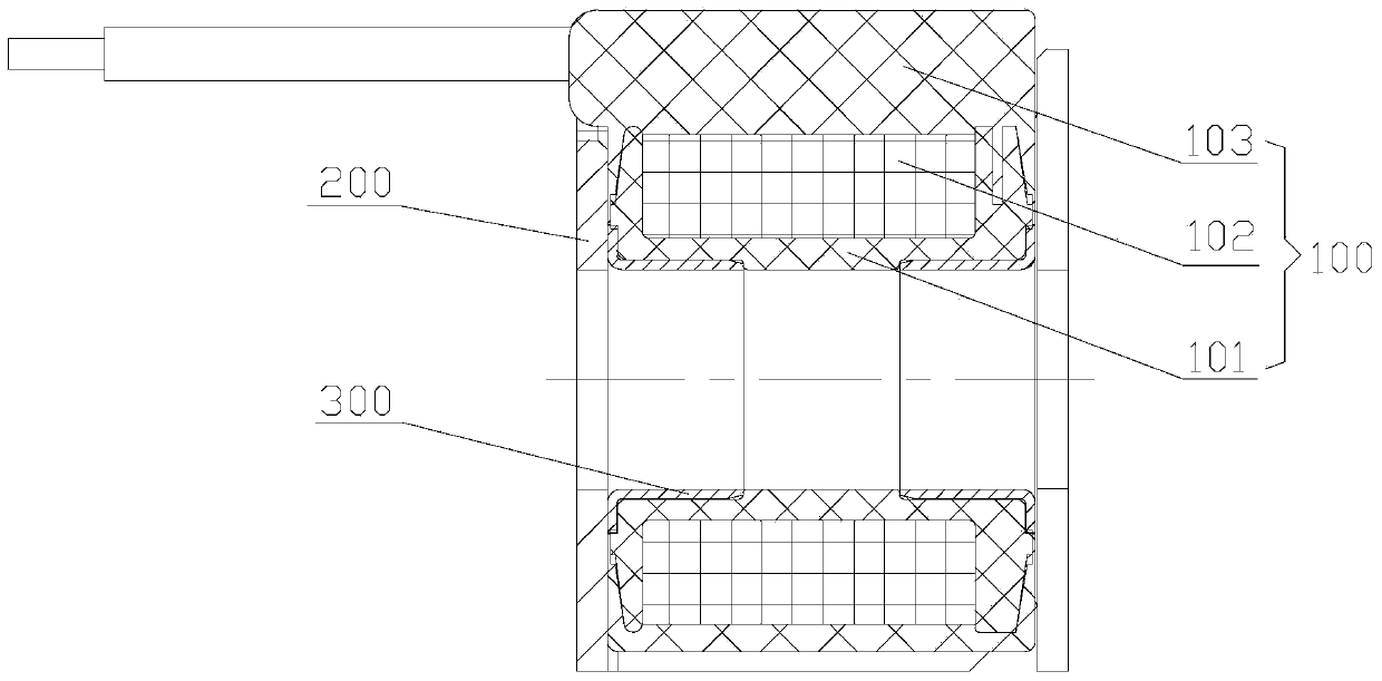
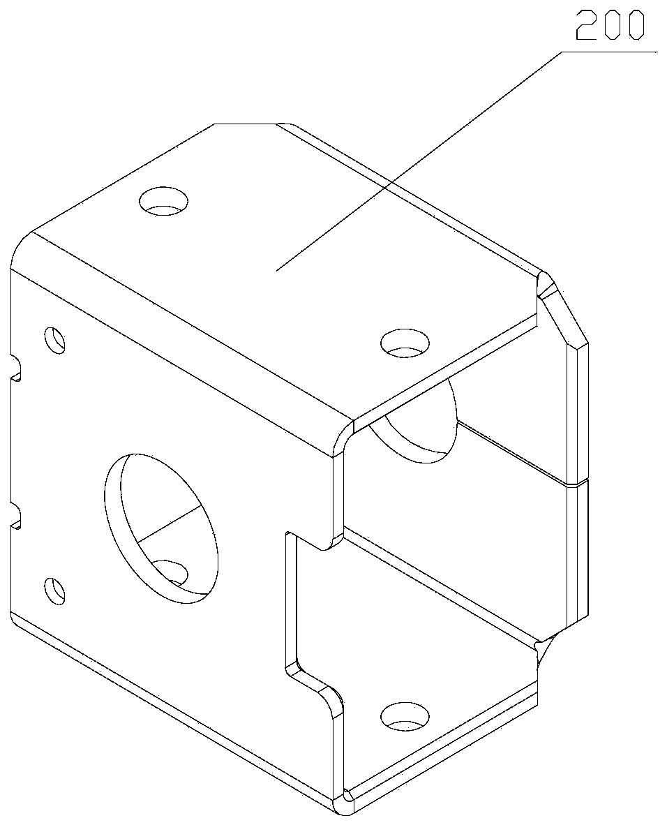
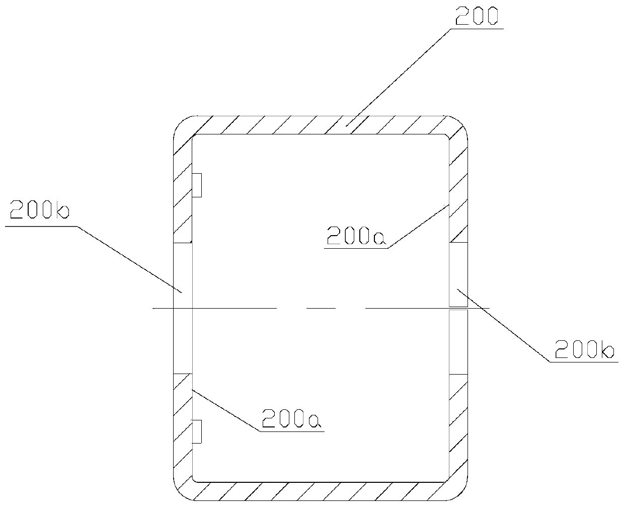
[0052] Please refer to Figure 8- Figure 9 , Figure 8-1 , Figure 8-2 and Figure 8-3 It shows the assembly process of a magnetic permeable component and a coil component provided by the present invention, Figure 9 A cross-sectional view of the assembled electromagne...


PUM


Abstract

The invention discloses a magnetic conductive assembly of an electromagnetic coil. The magnetic conductive assembly of the electromagnetic coil comprises two magnetic conductive parts which are equipped with end plates; each end plate is equipped with a through hole which is in match with an inner hole in a coil part; at least one of the two end plates is fixedly equipped with a magnetic conductive sleeve which is inserted into the inner hole; two magnetic conductive parts sleeve the coil part to be fixedly connected; the magnetic conductive assembly is of a split type structure; the magnetic conductive parts and the magnetic conductive sleeves are integrally arranged; when in assembling, the inner end surfaces of the magnetic conductive parts are reliably clung to the end surfaces of the coil parts, so that the electromagnetic noise produced between the magnetic conductive parts and the coil part or between the magnetic conductive parts and the magnetic conductive sleeves in the background technology can be avoided; in addition, each magnetic conductive sleeve is inserted into the inner hole of the coil part, so that the relative positions of the magnetic conductive parts and the coil part is limited; the two magnetic conductive parts are fixedly connected are being assembled, thus the magnetic conductive assemblies are reliably located to the coil part, and the quality problem that the magnetic conductive assembly and the coil part are separated and even fallen down during being transported can be avoided. The invention also discloses an electromagnetic coil comprising the magnetic conductive assembly.

Description

technical field [0001] The invention relates to the technical field of electromagnetic valves, in particular to an electromagnetic coil for an electromagnetic valve and a magnetic conduction assembly thereof. Background technique [0002] The most basic performance indicators of the electromagnetic coil are the minimum operating voltage and temperature rise; among them, the lower the minimum operating voltage, the more reliable the operating performance of the electromagnetic coil, and the electromagnetic coil can work within a larger voltage fluctuation range; the lower the temperature rise, It shows that the heat dissipation of the electromagnetic coil is good, which is beneficial to prolong the service life of key components such as the skeleton, the package and the enameled wire, and the low temperature rise can in turn improve the reliability of the operation. In addition, the electromagnetic noise generated when the electromagnetic coil is energized has also become a p...

Claims


Application Information

Patent Timeline
Patent Type & Authority Applications(China)
IPC IPC(8): F16K31/06H01F5/00
CPCF16K31/0675H01F7/121H01F7/126
Inventor 不公告发明人
Owner ZHEJIANG SANHUA CLIMATE & APPLIANCE CONTROLS GRP CO LTD
Why Eureka
Try Eureka