Automatic three-dimensional measuring method and automatic three-dimensional measuring system for high-precision blade of aviation engine

An aero-engine, three-dimensional measurement technology, applied in the field of precision measurement, can solve the problems of measurement results, low measurement accuracy, and measurement data accuracy.

Active Publication Date: 2015-04-15
HUAZHONG UNIV OF SCI & TECH
View PDF7 Cites 61 Cited by
  • Summary
  • Abstract
  • Description
  • Claims
  • Application Information

AI Technical Summary

Problems solved by technology

The time-of-flight method (also known as the light section method) uses a line laser to scan the surface of the free-form surface. One measurement can obtain the three-dimensional data points of a line on the measured surface, thereby improving the measurement efficiency, but its measurement accuracy is lower than that of aviation blades. Testing requirements
Moreover, the surface of the turbine blades of the aero-engine may have been forged, rolled or polished, and some parts are very bright. When using the time-of-flight method to measure the surface of highly reflective objects, the specular reflection on the surface of the object will greatly affect the measurement results
[0006] The structured light projection method is also used in the free-form surface measurement process. The measurement speed of the st

Method used


Image

  • Automatic three-dimensional measuring method and automatic three-dimensional measuring system for high-precision blade of aviation engine
  • Automatic three-dimensional measuring method and automatic three-dimensional measuring system for high-precision blade of aviation engine
  • Automatic three-dimensional measuring method and automatic three-dimensional measuring system for high-precision blade of aviation engine

Examples


Embodiment Construction

[0059] In order to make the object, technical solution and advantages of the present invention clearer, the present invention will be further described in detail below in conjunction with the accompanying drawings and embodiments. It should be understood that the specific embodiments described here are only used to explain the present invention, not to limit the present invention. In addition, the technical features involved in the various embodiments of the present invention described below can be combined with each other as long as they do not constitute a conflict with each other.

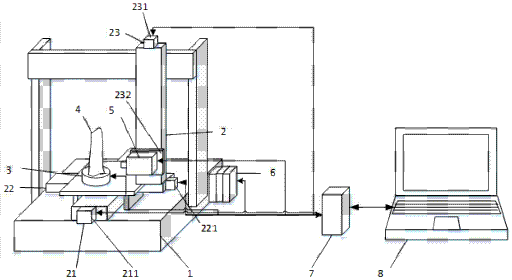
[0060] Such as figure 1 As shown, a high-precision automatic three-dimensional measurement system for aeroengine blades includes a motion support platform 1; a three-axis motion mechanism 2 installed on the motion support platform 1; a rotary table 3 installed on the three-axis motion mechanism 2; The tooling 4 is installed on the rotary table 3, including the cylindrical section and the fixtur...


PUM


Abstract

The invention discloses an automatic three-dimensional measuring method for a high-precision blade of an aviation engine. The automatic three-dimensional measuring method comprises the following steps of (1) rectification: performing rectification on a design coordinate system of a design model and a measurement coordinate system of a workpiece entity; (2) path planning: planning a motion path of a distance sensor in a measuring process by using a data processing device so that a measured region of the workpiece entity is in a measurement range of the distance sensor; and (3) automatic measurement: sampling a front region and a reverse region of the workpiece entity by using the distance sensor to obtain a complete surface profile of the workpiece entity. The distance sensor serves as a measuring terminal, and position information of surface points of the measured region can be acquired; and moreover, by a three-axis motion mechanism, measurement on different regions of the workpiece entity can be realized, measured cloud data of points of density of a local range are automatically fused to the same coordinate system, and complete precise measurement on a workpiece and quality testing operation on the workpiece entity are realized.

Description

technical field [0001] The invention belongs to the field of precision measurement, and more specifically relates to a high-precision automatic three-dimensional measurement method and system for aeroengine blades. Background technique [0002] With the vigorous development of the domestic aerospace field, the three-dimensional measurement technology of aeroengine blades has more and more extensive application prospects in aerospace, weaponry and other fields. [0003] The proper functioning of each turbine in a modern airliner or military jet depends on the error-free function of more than a thousand turbine rotor blades and guide vanes. In such cases, the highest quality standard can only be measured in microns. Therefore, these highly complex components with irregular surface topography have very tight tolerances. [0004] Take the measurement of aerospace blades as an example. At present, most domestic enterprises still use manual inspection to measure blades. This met...

Claims


Application Information

Patent Timeline
IPC IPC(8): G01B11/24
Inventor 李中伟史玉升程旭
Owner HUAZHONG UNIV OF SCI & TECH
Why Eureka
Try Eureka