
Medical operating magnifier

A magnifying glass and surgery technology, which is applied in the field of medical surgical magnifying glass, can solve the problems that the surgeon's neck is prone to fatigue, does not have the ability to change the magnification and object imaging orientation, and does not have the ability to change the magnification and object imaging direction, etc., to achieve the benefits of cervical spine Healthy, intuitive operation, and the effect of reducing the burden on the cervical spine

Inactive Publication Date: 2015-04-15
SHANGHAI TONGJI HOSPITAL
View PDF9 Cites 6 Cited by
  • Summary
  • Abstract
  • Description
  • Claims
  • Application Information

AI Technical Summary

Problems solved by technology

[0004] Chinese patent document CN103163654A, the patent name is "a new type of magnifying glasses for surgery", which discloses a new type of magnifying glasses for surgery, which are small in size and simple in structure. The patient's neck is prone to fatigue, and it does not have the function of changing the magnification and the imaging direction of the object
[0005] Chinese patent document CN103163654A, the patent name is "multifunctional surgical magnifying glass", discloses a multifunctional surgical magnifying glass, which can switch between the magnifying glass and glasses without removing the frame, but does not have the function of changing the magnification and the imaging orientation of the object
[0008] In summary, there is an urgent need for a medical surgical magnifier that can protect the cervical spine, change the optical path, magnify the object image, and adjust the angle of the objective lens at will, but there is no report about this medical surgical magnifier.

Method used


Image

  • Medical operating magnifier
  • Medical operating magnifier
  • Medical operating magnifier

Examples


Embodiment 1

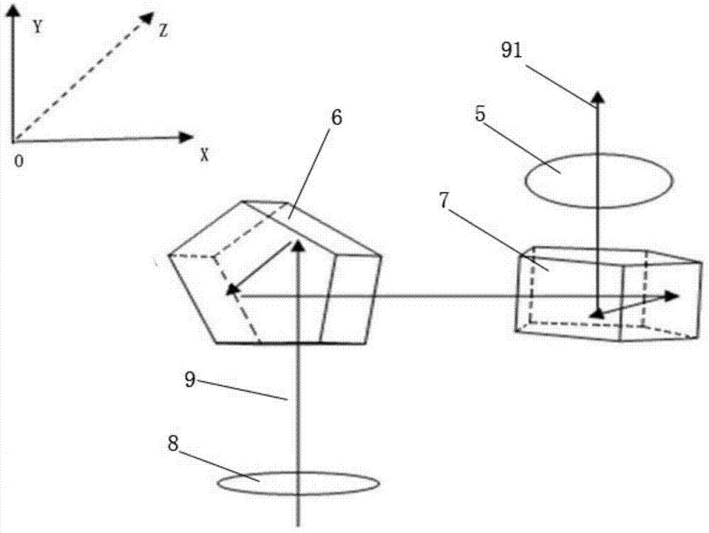
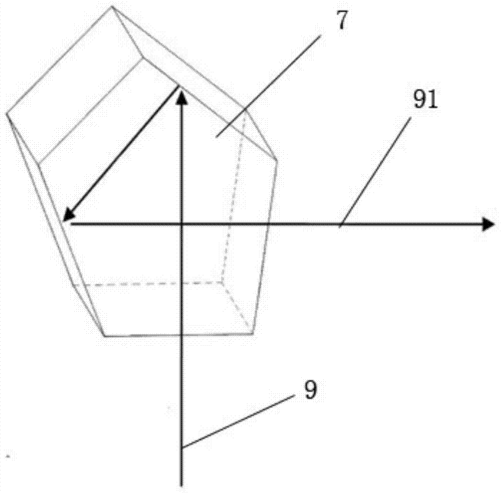
[0040] For ease of description, the following description uses the terms "proximal", "distal", "X-axis", "Y-axis", "Z-axis", "sagittal", "coronal", where the " Near end” refers to the end near the operation, and the “far end” refers to the end far away from the operation; the direction of the “Y axis” is the direction of the incident light, and the direction of the “Z axis” is the direction of the operator The direction of vision, the "X-axis" direction is perpendicular to the direction of incident light, and the direction perpendicular to the direction of vision; the "sagittal position" refers to the section perpendicular to the ground along the anteroposterior diameter of the body; The "coronal position" refers to a section perpendicular to the ground along the left and right diameters of the body.

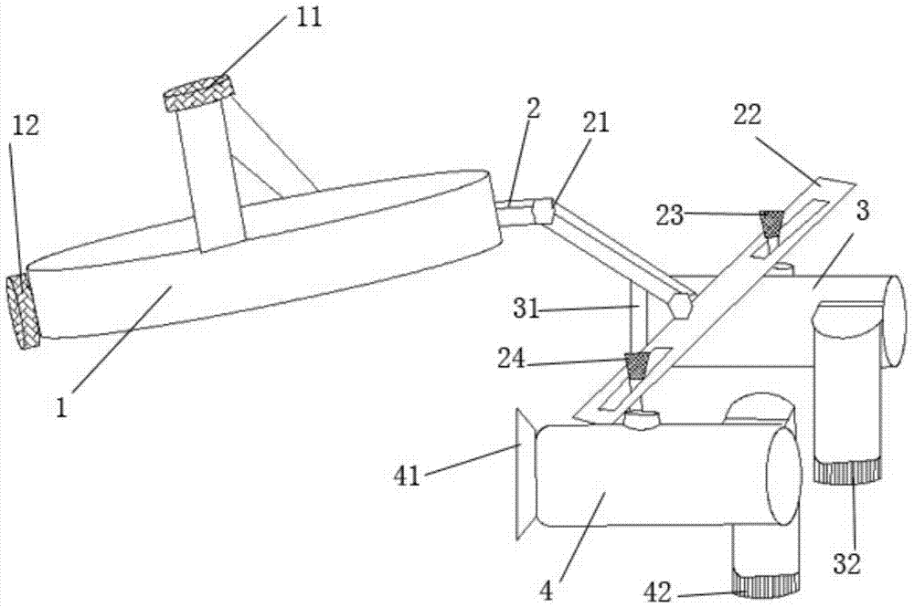
[0041] Please refer to figure 1 , figure 1 It is a structural schematic diagram of a medical operating magnifying glass of the present invention. A medical surgical magnifyin...


PUM


Abstract

The invention relates to a medical operating magnifier which is provided with a head fixing frame, wherein the head fixing frame is connected with a beam through a connecting rod; the connecting rod is connected with the head fixing frame and the beam through two kinematic pairs; a left pupil distance regulation knob and a right pupil distance regulation knob are connected to the beam; the left pupil distance regulation knob is fixed on a left lens cone; the right pupil distance regulation knob is fixed on a right lens cone; a left eyepiece is mounted at the proximal end of the left lens cone, and a right eyepiece is mounted at the proximal end of the right lens cone; a left object lens is mounted at the distal end of the left lens cone, and a right object lens is mounted at the distal end of the right lens cone; a concave lens, a second pentaprism, a first pentaprism and a convex lens are sequentially mounted from the proximal end to the distal end of each of the left and right lens cones. The medical operating magnifier has the advantages that a microscope operator is not required to lower the head for a long time, so that the burden of the cervical vertebrae of the microscope operator is reduced, and the medical operating magnifier is favorable for cervical health; the concave lenses are combined with the convex lenses, so that a magnified and erected virtual image can be presented, and direct operation is facilitated.

Description

technical field [0001] The invention relates to the technical field of medical optical instruments, in particular to a medical operating magnifying glass. Background technique [0002] Surgical magnifying glass is a kind of medical auxiliary equipment widely used in clinic, widely used in microdiagnosis and treatment operations in ophthalmology, facial features, stomatology, plastic surgery, general surgery and other departments. [0003] During the operation, the surgical magnifying glass sometimes requires the medical staff to keep the head in a certain position for observation, and cannot keep the head upright, slightly backward or the most comfortable neck posture for the individual. If the time is too long, it will easily cause cervical disc degeneration, Cervical spondylosis such as protrusion, cervical hyperosteogeny, etc.; secondly, surgical magnifying glasses need to be observed from different directions and angles during auxiliary treatment, and the incident light ...

Claims


Application Information

Patent Timeline
Patent Type & Authority Applications(China)
IPC IPC(8): G02B25/00
CPCG02B25/007
Inventor 毕燕龙刘振兴周祁施青陈冉冉刘歆
Owner SHANGHAI TONGJI HOSPITAL
Learn More