Current collector for a flow battery

A liquid flow battery and current collector technology, which is applied in the field of current collectors, can solve problems such as flow dead zone, battery concentration polarization deterioration, and electrolyte utilization reduction, and achieve simple preparation process, reduced electrode thickness, and reduced ohmic internal energy. The effect of resistance

Active Publication Date: 2017-08-11
DALIAN INST OF CHEM PHYSICS CHINESE ACAD OF SCI
View PDF5 Cites 0 Cited by
  • Summary
  • Abstract
  • Description
  • Claims
  • Application Information

AI Technical Summary

Problems solved by technology

[0005] When the electrolyte of a flow battery flows inside the battery, it is prone to uneven flow distribution and even flow dead zones. degradation, and even affect battery life

Method used


Image

  • Current collector for a flow battery
  • Current collector for a flow battery
  • Current collector for a flow battery

Examples


Embodiment

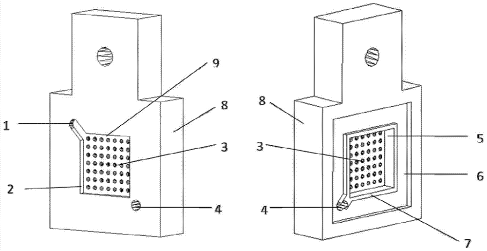
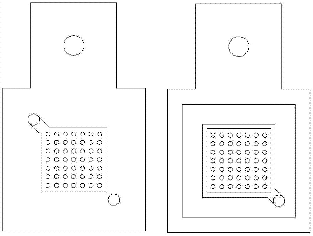
[0032] The thickness of the current collector is 15mm, and the length and width are 50mm; the length and width of the liquid storage groove and the electrode groove are both 30mm; the depth of the liquid storage groove is 1mm; the depth of the electrode groove is 3mm, and the seepage hole is a circular hole structure with a diameter of 1mm , The density of holes in the diagonal area of ​​the liquid in and out is small, and the hole density in the area away from the diagonal line is large; the depth of the sealing groove on the outer edge of the electrode groove is 1mm, and the width of the sealing groove is 1.5mm. The electrode size (length×width×thickness) used in the assembly of the flow battery is 30mm×30mm×6mm, and the electrode compression-stretch ratio is 2; the sealing element is in the shape of a rectangular ring with a thickness of 1mm and a width of 1mm around it. The energy efficiency of the battery tested under the condition of 80mAcm-2 is 81.25%, which is 1% higher...


PUM

PropertyMeasurementUnit
widthaaaaaaaaaa
thicknessaaaaaaaaaa
thicknessaaaaaaaaaa

Abstract

The invention relates to a current collector for a liquid flow battery, which is a plate-shaped structure. Grooves are respectively provided on the two side surfaces of the current collector. The grooves on one side are liquid storage grooves, and the grooves on one side are electrode grooves. The groove, the liquid storage groove and the electrode groove are arranged oppositely on the two side surfaces of the current collector, and a through hole is provided at the bottom of the opposite groove as a seepage hole, and the liquid storage groove and the electrode groove are connected through the seepage hole Pass. This current collector structure has the advantages of high battery efficiency, non-uniform distribution of seepage holes, and uniform distribution of liquid flow along the radial direction; at the same time, the liquid flow frame is omitted, the number of sealing components is reduced, the electrode thickness is reduced, and the design and preparation process is simple. , the cost is lower.

Description

[0001] 【Technical field】 [0002] The invention relates to the field of redox flow batteries, in particular to a current collector for a flow battery. [0003] 【Background technique】 [0004] With the gradual depletion of primary energy and the aggravation of environmental problems, human needs for renewable energy have become more and more urgent. Renewable energy has gradually changed from tutoring energy to dominant energy, providing energy support for human survival and development. Among renewable energy sources, wind power and solar power are the most widely used. However, wind power generation has the characteristics of discontinuity and instability. In order to ensure the power quality and the safe operation of the power grid, the development of energy storage technology is particularly critical. Among large-scale energy storage technologies, flow batteries have the advantages of independently adjustable power and capacity, deep discharge, and high energy efficiency,...

Claims


Application Information

Patent Timeline
Patent Type & Authority Patents(China)
IPC IPC(8): H01M8/0258
CPCH01M8/026Y02E60/50Y02P70/50
Inventor 张华民郑琼邢枫
Owner DALIAN INST OF CHEM PHYSICS CHINESE ACAD OF SCI
Why Eureka
Try Eureka