Systems, apparatus, equipment with thermal disinfection and thermal disinfection methods

A heat disinfection and water supply system technology, applied to chemical instruments and methods, disinfection, dialysis systems, etc., to achieve the effects of reducing energy consumption, time reduction, and burden reduction

Active Publication Date: 2015-04-15
GAMBRO LUNDIA AB
View PDF6 Cites 6 Cited by
  • Summary
  • Abstract
  • Description
  • Claims
  • Application Information

AI Technical Summary

Problems solved by technology

As a result, when staff are working three shifts

Method used


Image

  • Systems, apparatus, equipment with thermal disinfection and thermal disinfection methods
  • Systems, apparatus, equipment with thermal disinfection and thermal disinfection methods
  • Systems, apparatus, equipment with thermal disinfection and thermal disinfection methods

Examples


Embodiment Construction

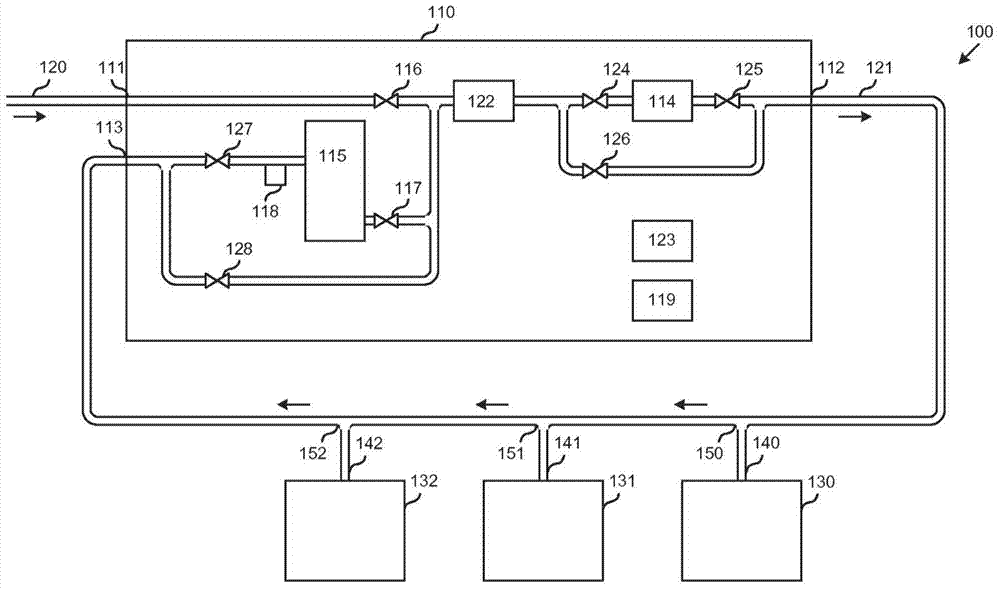
[0023] figure 1A schematic diagram of a water supply system 100 according to a first embodiment of the present invention is shown. The water supply system 100 includes a water treatment unit 110 connected to a water inlet pipe 120 at a treatment unit inlet 111 . The pipe loop arrangement 121 is connected to the treatment unit outlet 112 and the water return inlet 113 of the water treatment unit 110 . Medical devices such as dialysis devices 130 , 131 and 132 are connected to the tubing circuit arrangement 121 via dialysis device connectors 150 , 151 and 152 and dialysis device connection tubes 140 , 141 and 142 . Within the water treatment unit 110 , a first side of a first valve 116 is connected to the treatment unit inlet 111 . The second side of the first valve 116 is connected to the inlet of the pump 122 of the pump 122 . An outlet of the pump 122 is connected to a first side of a third valve 124 and a first side of a fifth valve 126 . The second side of the third val...


PUM


Abstract

Water systems, medical equipment, and apparatus for thermal disinfection comprise a control unit which starts the disinfection of a fluid path by controlling a heating unit to heat water and controlling an actuator to enable heated water to flow into the fluid path. The control unit reads the temperature as measured by a temperature sensor during the disinfection and calculates an achieved disinfection dose. The achieved disinfection dose is compared with a set disinfection dose and the disinfection is discontinued if the achieved disinfection dose corresponds to the set disinfection dose.

Description

technical field [0001] The invention relates to water supply systems, medical devices, such as dialysis units, as well as devices for thermal disinfection and methods for thermal disinfection. Background technique [0002] There are several types of procedures for drawing blood in an extracorporeal blood circuit. These treatments involve, for example, hemodialysis, hemofiltration, hemodiafiltration, plasma withdrawal, blood component separation, blood oxygenation, and the like. Typically, blood is withdrawn from the vessel at the puncture site and returned to the same vessel or to a vessel elsewhere in the body. [0003] In the case of hemodialysis, the treatment fluid, also called dialysis fluid, is made nearly isotonic with the patient's blood. Treatment fluid and the patient's blood are allowed to flow on each side of the semipermeable membrane of a membrane device, called a dialyzer. Diffusive transfer from one side of the membrane to the other is achieved when the co...

Claims


Application Information

Patent Timeline
IPC IPC(8): A61M1/16A61L2/04C02F1/02
CPCC02F1/02C02F2209/44A61M1/1686A61L2/04A61M2205/3368C02F2103/026C02F2301/046A61M1/1688C02F2209/02C02F2303/04A61M2205/36A61L2/24C02F1/008G05B15/02G05D7/0629
Inventor 安德斯·费尔丁托尔-比约恩·约纳松丹·乔森拉尔夫·尼斯特兰德
Owner GAMBRO LUNDIA AB
Why Eureka
Try Eureka