Active cooling of a motor

An electronic and stator technology, which is applied in the direction of cooling/ventilation devices, connection with control/drive circuits, electromechanical devices, etc., can solve problems such as hindering the circulation of motors and electronic housings, and difficulties in effective cooling of motors or electronic components. sealing effect

Active Publication Date: 2015-04-15
EBM PAPST MULFINGEN GMBH & CO KG
View PDF5 Cites 2 Cited by
  • Summary
  • Abstract
  • Description
  • Claims
  • Application Information

AI Technical Summary

Problems solved by technology

This type of fixing makes it difficult to effectively cool the motor or the electronic components, becaus...

Method used


Image

  • Active cooling of a motor
  • Active cooling of a motor
  • Active cooling of a motor

Examples


Embodiment Construction

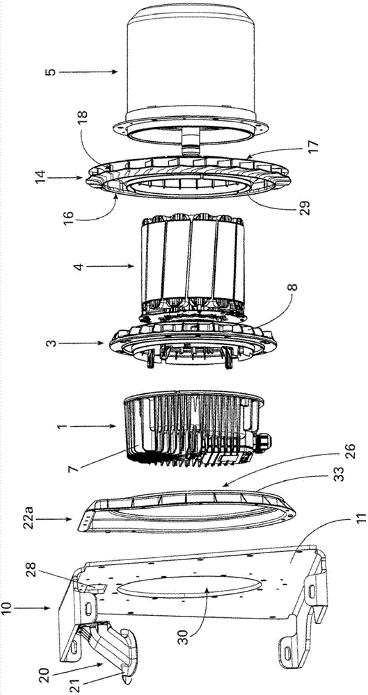
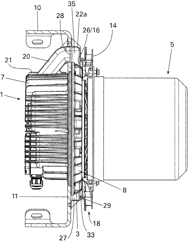
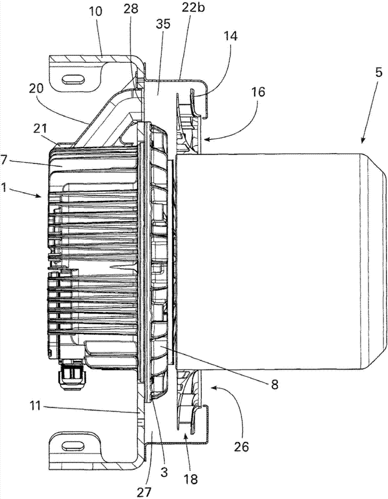
[0022] figure 1 , figure 2 and image 3 An electric machine according to the invention, in particular an external rotor electric machine, is shown in each case. The electric machine comprises an electronics housing 1 , a stator comprising a stator bushing 3 and a stator laminated core 4 with motor coils, and a rotor 5 (in particular an outer rotor). The stator bushing 3 and the electronics housing 1 consist in particular of metal. Furthermore, electromechanical electronics for driving and controlling the electric motor, in particular commutation electronics with electrical power components such as output stages, are located in the electronics housing 1 . The electronics housing 1 has housing cooling fins 7 on its outer wall for cooling electronic components (not shown) inside the electronics housing 1 . The stator bush 3 has on its outer wall radially extending stator cooling fins 8 which dissipate the heat generated by the stator, in particular by ball bearings (not show...


PUM


Abstract

The invention relates to a motor, comprising an electronics housing (1), a stator having a stator bushing (3), and a rotor (5). The motor can be fastened to a fastening wall (11) by means of the stator bushing (3). The motor according to the invention has an air conducting element and an air conveying element (14). The air conveying element is connected to the rotor (5) in a rotationally fixed manner. The air conducting element (22a) surrounds the stator bushing (3) and forms a flow space (35) between the air conducting element (22a) and an outer circumference of the stator bushing (3). The flow space (35) is open on the side of the electronics housing (1) in the direction of the fastening wall (11) through at least one flow gap (27). The air conducting element (14) opens with an intake opening (16) via a sealing gap in a rotor-side throughflow opening (26) of the air conducting element.

Description

technical field [0001] The invention relates to an electric machine comprising an electronics housing, a stator with a stator bushing and a rotor, wherein the electric machine can be fastened to a fixed wall by means of the stator bushing. Background technique [0002] Such motors are used in particular to drive fans and have integrated electronics (in particular commutation electronics). The maximum power range of the electric machine is usually limited by the maximum component temperature of the electronics (for example the temperature of an electrical power component such as an output stage) or the maximum component temperature of the electric machine (for example the temperature of the motor coils or ball bearings). The service life of the electric machine also depends on the component temperatures reached during operation of the electric machine, wherein increased temperatures shorten the service life of the electric machine. [0003] These motors are in particular fas...

Claims


Application Information

Patent Timeline
IPC IPC(8): H02K11/00
CPCH02K9/14H02K5/20H02K5/18H02K11/0073H02K11/33H02K5/207H02K9/06
Inventor 克里斯蒂安·哈格斯文·瓦尔特比约恩·萨德勒奥利弗·哈夫
Owner EBM PAPST MULFINGEN GMBH & CO KG
Why Eureka
Try Eureka