Deep ploughing, deep scarification and ridge smashing device

A technology of powder ridge and deep loosening, which is applied in the fields of tillage equipment, application, agricultural machinery and equipment, etc., can solve the problems of poor soil crushing effect, slow plowing speed, and large rotation resistance, and achieves reduced resistance, good effect, high speed quick effect

Inactive Publication Date: 2015-04-22
GUANGXI WUFENG MACHINERY CO LTD
View PDF6 Cites 24 Cited by
  • Summary
  • Abstract
  • Description
  • Claims
  • Application Information

AI Technical Summary

Problems solved by technology

[0003] The technical problem solved by the present invention is that the deep plowing deep loosening powder ri

Method used


Image

  • Deep ploughing, deep scarification and ridge smashing device
  • Deep ploughing, deep scarification and ridge smashing device

Examples


specific Embodiment approach 1

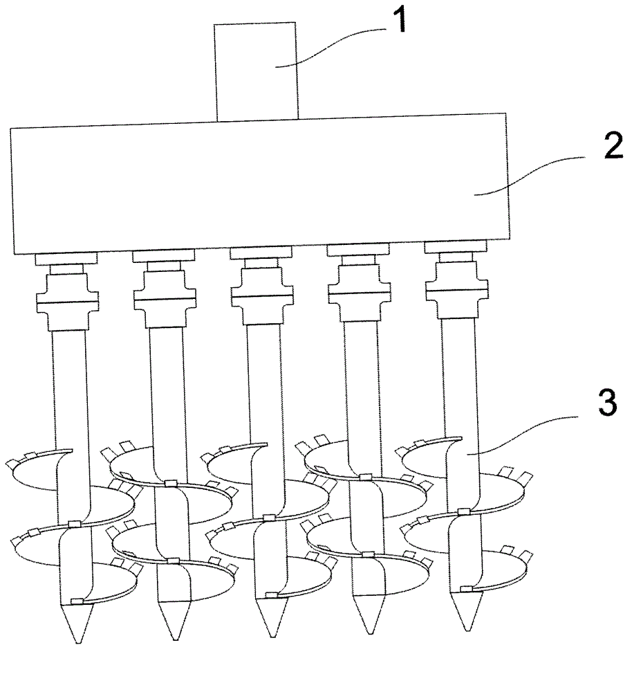
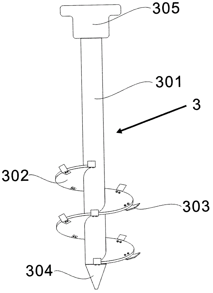
[0014] The device comprises a hydraulic motor 1, a gear transmission case 2 and 5 powder ridge drill bits 3, and the deep plowing and deep loosening powder ridge device can adjust the number of powder ridge drill bits according to the size of the powder ridge area. The power of the hydraulic motor 1 is transmitted to the powder ridge drill bit through the gear transmission box 2. The gears in the transmission box are closely arranged, and the rotation directions of the two adjacent gear shafts are opposite. Among them, the first, third and fifth drill bits Rotate clockwise, the 2nd and 4th drill bits rotate counterclockwise, the spiral direction of the powder ridge blades of the 1st, 3rd and 5th powder ridge drill bits is the same as that of the 2nd and 4th powder ridge drill bits The helical direction of the powder ridge blades is opposite, so that the soil moves upwards along the drill bit, which reduces the travel resistance of the powder ridge drill bit and deep plowing and...

specific Embodiment approach 2

[0017] Such as figure 1 The shown deep plowing and deep loosening powder ridge device includes an electric motor, a transmission box and 3 powder ridge drill bits. The deep plowing and deep loosening powder ridge device can adjust the number of powder ridge drill bits according to the size of the powder ridge area. The power of the hydraulic motor 1 is transmitted to the powder ridge drill bit through the gear transmission box 2. The gears in the transmission box are closely arranged, and the rotation directions of the two adjacent gear shafts are opposite, and the first and third drill bits rotate clockwise. The 2nd drill bit rotates counterclockwise, and the helical direction of the powder ridge blades of the powder ridge drill bits 1 and 3 is opposite to the helical direction of the powder ridge blades of the powder ridge drill bit 2. The soil moves upward along the drill bit, reducing the traveling resistance of the powder ridge drill bit and the deep plowing and deep loos...


PUM


Abstract

The invention provides a deep ploughing, deep scarification and ridge smashing device which aims to solve the problems that a ridge smashing machine is low in traveling speed, low in efficiency and the like. The deep ploughing, deep scarification and ridge smashing device comprises a driving motor, a gear transmission case and at least two ridge smashing drill bits. The power of the motor is transmitted to the ridge smashing drill bits through the transmission case. Each ridge smashing drill bit comprises a screw shaft, a screw blade, ridge smashing cutters, a drill tip and a connecting flange. The screw blades are mounted on the screw shafts, every two adjacent ridge smashing drill bits rotate reversely, and the screw directions of the screw blades are opposite. The ridge smashing device using the ridge smashing drill bits is higher in ploughing speed, better in soil smashing effect and natural ridging effect, capable of meeting the using requirements of agricultural production and suitable for mass production.

Description

technical field [0001] The invention belongs to the field of agricultural tillage machinery, and in particular relates to an agricultural deep tillage powder ridge machine. Background technique [0002] Notification number: CN2549700Y utility model patent application discloses a rotary tillage plow, the body of the plow is provided with a longitudinal driving shaft, a drilling and milling head is installed under the driving shaft, the driving shaft is connected with external power through a transmission device, and the drilling and milling head Driven by the power, it rotates at a high speed, which can effectively drill into the ground, and at the same time move forward under the drive of the tractor to complete the farming. Publication number: CN 101971723 A application for an invention patent titled: The invention patent discloses a powder ridge mechanical drill bit, the rotary atherectomy drill device is equipped with one or more drill shafts, the drill shaft is equipped ...

Claims


Application Information

Patent Timeline
IPC IPC(8): A01B33/06A01B33/10
Inventor 李阳铭
Owner GUANGXI WUFENG MACHINERY CO LTD
Why Eureka
Try Eureka