Straight-line motion manipulator

A technology of linear motion and manipulators, applied in the direction of manipulators, program-controlled manipulators, chucks, etc., can solve the problems of high price, short life of mechanical fingers, complex structure, etc., and achieve the effect of small frictional resistance, long life and stable operation

Inactive Publication Date: 2015-04-22
WENZHOU POLYTECHNIC
View PDF7 Cites 1 Cited by
  • Summary
  • Abstract
  • Description
  • Claims
  • Application Information

AI Technical Summary

Problems solved by technology

[0004] However, the existing mechanical fingers are often driven by motors, which are compl

Method used


Image

  • Straight-line motion manipulator
  • Straight-line motion manipulator
  • Straight-line motion manipulator

Examples


Embodiment Construction

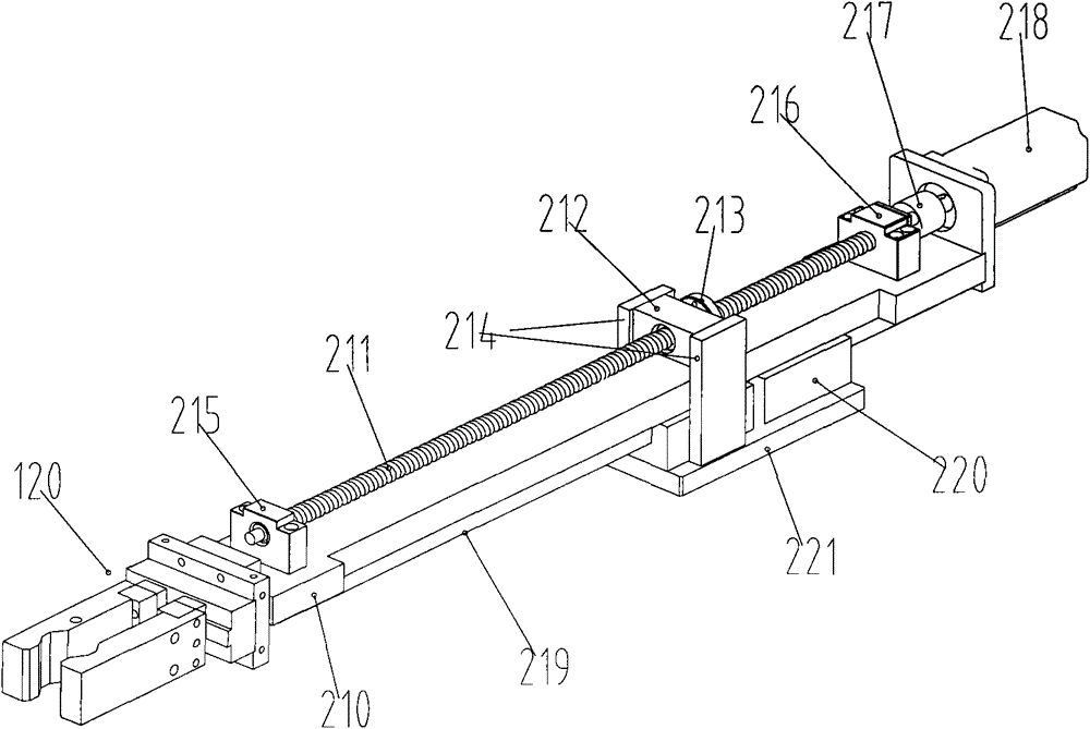
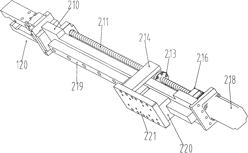
[0031] The present invention will be further described in detail below in conjunction with the accompanying drawings, but does not constitute any limitation to the present invention. Similar component numbers in the accompanying drawings represent similar components. As mentioned above, the present invention provides a rail-type manipulator for grasping and transferring materials.

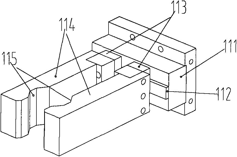
[0032] figure 1 , figure 2 It is a structural schematic diagram of the linear motion manipulator of the present invention, image 3 It is a structural schematic diagram of the claw of the linear motion manipulator of the present invention, Figure 4 , Figure 5 , Figure 6 It is a structural schematic diagram of the slider module of the linear motion manipulator of the present invention, Figure 7 yes Figure 5 The schematic diagram of the structure of the slider module of the linear motion manipulator of the present invention at the cross section at A, Figure 8 yes Figure 6 Shown is a s...


PUM


Abstract

The invention relates to industrial automation devices, in particular to an automated manipulator. A straight-line motion manipulator comprises an arm and a paw; the paw is fixedly connected to one end of the arm; the arm comprises a bottom plate, a lead screw, a long guide rail, a square slider, a nut, a servo motor and a coupling; one end of the lead screw is movably connected with a lead screw fixing seat, and the other end of the lead screw is movably connected with a lead screw supporting seat; the lead screw fixing seat and the lead screw supporting seat are fixedly connected to the bottom plate; the lead screw is parallel to the long guide rail; the paw comprises a slider module and fingers; the fingers are fixedly connected to sliders; the slider module comprises a finger body, a guide rail, pistons, a plunger pin and the sliders. The guide rail type manipulator is applicable to a machine manufacturing process, and is small in frictional resistance, stable in operation, high in precision and long in operating life, and carrying and transferring of materials are realized.

Description

technical field [0001] The invention relates to industrial automation equipment, more specifically, to an automatic manipulator. Background technique [0002] A manipulator refers to an automatic operating device that can imitate certain movement functions of the human hand and arm to grab, carry objects or operate tools according to a fixed program. It can replace human heavy labor to realize the mechanization and automation of production, and can operate in harmful environments to protect personal safety, so it is widely used in machinery manufacturing, metallurgy, electronics, light industry and atomic energy and other departments. [0003] The manipulator is mainly composed of three parts: hand, motion mechanism and control system. The hand is a part used to grasp the workpiece (or tool), and there are various structural forms according to the shape, size, weight, material and operation requirements of the grasped object, such as clamping type, holding type and adsorpti...

Claims


Application Information

Patent Timeline
IPC IPC(8): B25J9/00B25J15/08B25J9/14
Inventor 余胜东马金玉
Owner WENZHOU POLYTECHNIC
Why Eureka
Try Eureka