Chemical waste liquid treater

A processor and waste liquid technology, which is applied in water/sewage treatment, chemical instruments and methods, water/sewage treatment equipment, etc. Good ability to purify chemical waste liquid, long service life, long service life effect

Inactive Publication Date: 2015-04-22
PUYANG GUANGMING CHEM
View PDF7 Cites 0 Cited by
  • Summary
  • Abstract
  • Description
  • Claims
  • Application Information

AI Technical Summary

Problems solved by technology

[0002] Chemical waste liquid refers to the waste water produced in the process of producing products in chemical plants, such as oily waste water in the production of ethylene, polyethylene, rubber, polyester, methanol, ethylene glycol, oil tank farms, air separation and air compressor stations, etc. After biochemical treatment, it can generally meet the national secondary discharge standard. Due to the shortage of water resources, the water that meets the discharge standard needs to be further treated to meet the requirements of industrial water replenishment and reused. Since the impurities in the water are mainly suspended Particles and fine fibers, using the principle of mechanical filtration, adopts microporous filtration technology to remove impurities, and the working status of the processor equipment is controlled by electrical appliances to realize automatic backwashing and automatic operation. The pump is lifted to provide the water head required by the processor, and the effluent is directly introduced into the production system , the ordinary waste liquid processor has the disadvantages of low working efficiency, short service life, complex structure and difficult operation, etc. Therefore, a chemical waste liquid processor is proposed to solve the above problems

Method used


Image

  • Chemical waste liquid treater
  • Chemical waste liquid treater

Examples


Embodiment Construction

[0012] The following will clearly and completely describe the technical solutions in the embodiments of the present invention with reference to the accompanying drawings in the embodiments of the present invention. Obviously, the described embodiments are only some, not all, embodiments of the present invention. Based on the embodiments of the present invention, all other embodiments obtained by persons of ordinary skill in the art without making creative efforts belong to the protection scope of the present invention.

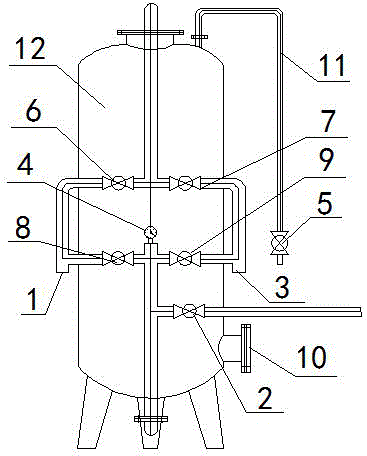
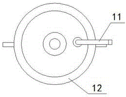
[0013] see Figure 1~2 , in an embodiment of the present invention, a chemical waste liquid processor, comprising a water inlet 1, an outlet valve 2, a drain 3, a pressure gauge 4, an exhaust valve 5, an upper inlet valve 6, an upper exhaust valve 7, and a lower inlet valve 8 , the lower discharge valve 9, the discharge port 10, the conduit 11 and the casing 12; the left end of the casing 12 is provided with a water inlet 1 and communicates with the upper ...


PUM


Abstract

The invention discloses a chemical waste liquid treater comprising a water inlet, a water outlet valve, a water outlet, a pressure gauge, an exhaust valve, an upper inlet valve, an upper outlet valve, a lower inlet valve, a lower outlet valve, a discharging hole, guide pipes and a shell, wherein the water inlet is formed in the left end of the shell, and the left end of the shell is communicated with the upper inlet valve and the lower inlet valve through the guide pipes; the pressure gauge is arranged between the lower inlet valve and the upper outlet valve, and the right side of the lower end of the pressure gauge is communicated with the water outlet valve through the guide pipe; the discharging hole is formed in the lower right end of the shell and is tightly connected with the lower right end of the shell; the water outlet is formed in the right end of the shell and is communicated with the lower outlet valve and the upper outlet valve; the upper outlet valve is located at the upper end of the lower outlet valve and is communicated with the upper inlet valve; and the exhaust valve is arranged at the right end of the shell, and the upper end of the exhaust valve is tightly connected and communicated with the top end of the shell through the guide pipe. The treater is good in treating effect, favorable in chemical waste liquid purifying capacity, high in work efficiency, long in service life and suitable for popularization and application.

Description

technical field [0001] The invention relates to the application field of waste liquid treatment technology, in particular to a chemical waste liquid processor. Background technique [0002] Chemical waste liquid refers to the waste water produced in the process of producing products in chemical plants, such as oily waste water in the production of ethylene, polyethylene, rubber, polyester, methanol, ethylene glycol, oil tank farms, air separation and air compressor stations, etc. After biochemical treatment, it can generally meet the national secondary discharge standard. Due to the shortage of water resources, the water that meets the discharge standard needs to be further treated to meet the requirements of industrial water replenishment and reused. Since the impurities in the water are mainly suspended Particles and fine fibers, using the principle of mechanical filtration, adopts microporous filtration technology to remove impurities, and the working status of the proces...

Claims


Application Information

Patent Timeline
Patent Type & Authority Applications(China)
IPC IPC(8): C02F9/04
CPCB01D24/105C02F1/281C02F1/5281C02F2201/002
Inventor 陈聚恩
Owner PUYANG GUANGMING CHEM
Why Eureka
Try Eureka