

Pressurizing and draining device applied to DNA synthesizer
A technology of liquid drainage device and synthesizer, which is applied in the direction of biochemical cleaning device, enzymology/microbiology device, bioreactor/fermenter combination, etc. It can solve the problem of no liquid drainage and cleaning links, reliable and stable liquid drainage device, etc. problem, to achieve the effect of speeding up the response
- Summary
- Abstract
- Description
- Claims
- Application Information
AI Technical Summary
Problems solved by technology
Method used
Image

Examples
Embodiment approach
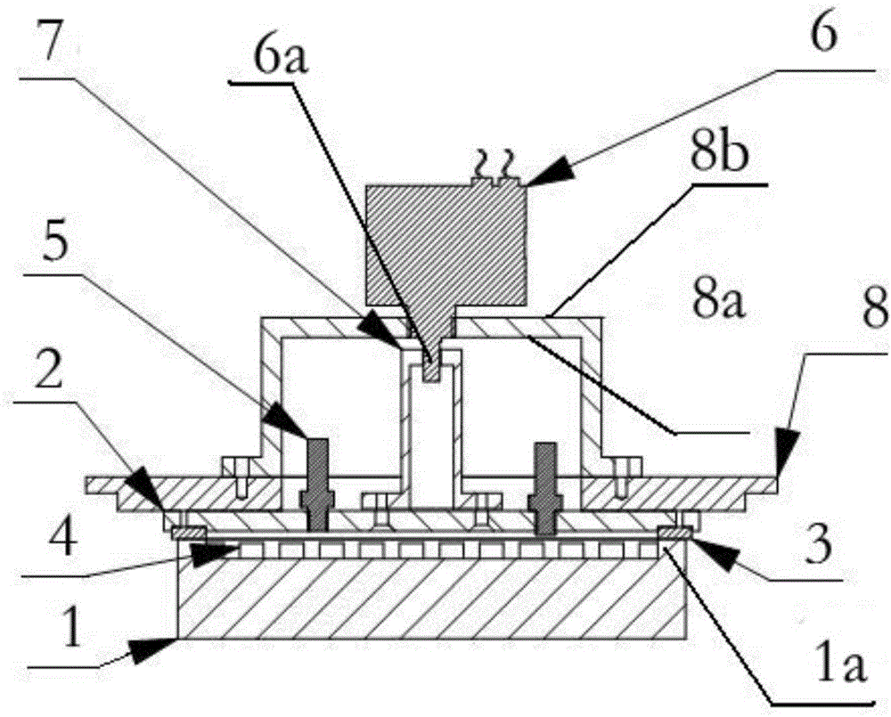
[0029] figure 1 As the first embodiment of the present invention, the pressurized liquid discharge drive device used in the present invention includes an electromagnetic drive mechanism 6 and an electromagnetic drive mechanism fixing seat, and the electromagnetic drive mechanism 6 is fixed on the electromagnetic drive mechanism fixing seat; The fixed seat of the electromagnetic drive mechanism 6 is installed on the periphery of the pressure plate 2; the lower end of the electromagnetic drive mechanism 6 is connected to the electromagnetic drive shaft 6a; connect.
[0030] The fixed seat of the electromagnetic drive mechanism includes a pressing fixing plate 8, a groove 8a and a protrusion 8b, the groove 8a is arranged on the lower surface of the pressing fixing plate 8, and the protrusion 8b is arranged with the On the upper surface of the pressure fixing plate 8 corresponding to the groove 8a; the electromagnetic drive shaft 6a passes through the protrusion 8b and enters the...
PUM
 Abstract
Description
Claims
Application Information