Vertical hydrapulper with drum groove body and spiral backflow plates

A hydraulic pulper, plate vertical technology, applied in the direction of textiles and papermaking, raw material separation, papermaking, etc., can solve the problems of uneven force on the tank body, reduced fiber friction, increased maintenance costs, etc., to achieve enhanced pulping Opportunity and effect, increase centripetal reaction force, effect of saving space and energy consumption

Inactive Publication Date: 2015-04-22
NANJING FORESTRY UNIV
View PDF5 Cites 4 Cited by
  • Summary
  • Abstract
  • Description
  • Claims
  • Application Information

AI Technical Summary

Problems solved by technology

[0007] 2. Pulping
[0010] 2. In terms of the setting of the slurry baffle, there is a design to set a vertical △-shaped baffle on the inner wall of the tank, which can block the circumferential flow of the slurry, and only rely on the △-shaped baffle to play part of the loose material and partially The material is guided horizontally to the central area, and cannot be guided to the bottom of the center, so that the material is easy to float on the surface of the pulp tank and reduce the contact with the rotor, which eventually leads to low pulping efficiency
Its shortcoming is that the deflectors arranged along the vortex movement direction of the paper material only play the role of diversion and upflow for the paper material, but cannot directly gener

Method used


Image

  • Vertical hydrapulper with drum groove body and spiral backflow plates
  • Vertical hydrapulper with drum groove body and spiral backflow plates
  • Vertical hydrapulper with drum groove body and spiral backflow plates

Examples


Example Embodiment

[0055] Example:

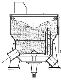
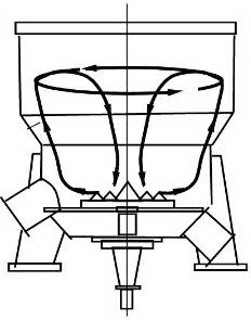
[0056] The vertical hydraulic pulper of the drum tank body spiral return plate of the present embodiment is as follows: Figure 11 As shown, the groove body is in the shape of a drum with a large middle and a small diameter at the upper and lower parts, including an upper straight body part 1, an upper ellipsoid body part 2 and a lower inverted cone part 3 that are connected in sequence. The height of the groove body is 1.0 to 1.2 times the diameter of the maximum end face, and the maximum end face diameter is located at the junction of the upper ellipsoid part 2 and the lower inverted cone part 3 .

[0057] The upper straight body part 1 is located at the top of the tank body, the tank wall is perpendicular to the bottom surface of the tank body, and its height accounts for about 18% of the height of the tank body, and the working liquid level is below the vertical wall surface.

[0058] The diameter of the upper ellipsoid portion 2 gradually increases from...


PUM

PropertyMeasurementUnit
Pitchaaaaaaaaaa
Angleaaaaaaaaaa

Abstract

The invention discloses a vertical hydrapulper with a drum groove body and spiral backflow plates. The vertical hydrapulper comprises the groove body and a rotor installed at the bottom of the groove body. The groove body is in a drum shape and comprises an upper ellipsoid part and a lower inverted cone part. The inner wall of the groove body is provided with the backflow plates arranged in an ascending spiral line mode. The rotating direction of the backflow plates is opposite to that of the rotor. Due to the groove body structure, the vertical hydrapulper has the good circulating, stirring, shearing and gathering functions on paper in the pulping process, and has the advantages of being small in energy loss, high in pulping efficiency, stable in operation and the like.

Description

technical field [0001] The invention relates to a pulper for mechanically processing papermaking fiber raw materials, in particular to a vertical hydraulic pulper with a drum groove body and a spiral backflow plate. Background technique [0002] The basic function of the hydropulper is to break pulp board, waste paper (cardboard), etc. into pulp under the condition of soaking in water through hydraulic and mechanical forces. The purpose of shredding is to disintegrate pulp board or waste paper (cardboard) into pulp fiber suspension, even if the fiber layer that was originally interwoven into paper sheets is dissociated into single fibers or fiber bundles to the greatest extent while maintaining The original shape and strength of the fiber. The crushing operation can separate heavy and large impurities from fibers. When processing waste paper that needs to be deinked, add a certain amount of deinking chemicals and heat it with steam to separate the fibers from the ink. [...

Claims


Application Information

Patent Timeline
IPC IPC(8): D21B1/34D21B1/32
CPCD21B1/32D21B1/345Y02W30/64
Inventor 张辉窦靖张放
Owner NANJING FORESTRY UNIV
Why Eureka
Try Eureka