Supercharge Your Innovation With Domain-Expert AI Agents!

Prestress concrete box girder end sealing formwork construction method

A technology of concrete box girder and construction method, applied in bridges, bridge construction, bridge materials, etc., can solve the problems of large investment in personnel and machinery, low safety performance, long construction period, etc., and achieves low cost investment, reduced pollution, and construction period short effect

Active Publication Date: 2015-04-22
CHINA RAILWAY NO 2 ENG GRP CO LTD +1
View PDF7 Cites 6 Cited by
  • Summary
  • Abstract
  • Description
  • Claims
  • Application Information

AI Technical Summary

Problems solved by technology

[0003] The existing construction method of bamboo plywood has low safety performance, long construction period, and is relatively complicated at the same time, and the investment of personnel and mechanical equipment is large, and there is also some pollution

Method used


Image

  • Prestress concrete box girder end sealing formwork construction method

Examples


Embodiment 1

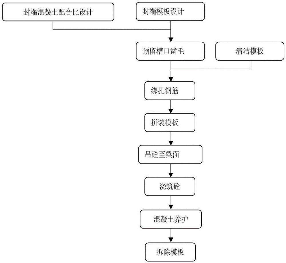
[0023] In this example, the structural form of the beam end and the actual situation on site (the adjacent beam gap width is 10cm, the pier height is 0.5m-18m, and there is no construction space on the top of the pier, etc.), the design uses 3mm steel plate as the panel of the formwork, and the angle steel ∠30× 4. The combined form of small steel molds used as ribs ensures sufficient rigidity of the formwork and at the same time solves the requirements of light weight and convenient operation;

[0024] The combined formwork (the formwork is welded by thin steel plate and angle steel as the back corrugation, and the whole set of formwork is reinforced by bolts, U-shaped clips, and tie rods) is divided into three parts: the inner and outer sides of the web, the bottom plate and the end formwork, all according to The beam profile designs its formwork shape. Among them, the bottom plate and the web formwork are designed to overlap 5cm inside, and the outside is close to the end fo...

Embodiment

[0055] Embodiment Benefits and advantages

[0056] 1 The overall design is the construction method of transporting concrete under the bridge - mechanical lifting - pouring concrete on the bridge deck, which not only solves the technical problem that concrete trucks cannot go on the bridge for construction, but also forms a cyclic operation system with a short construction period.

[0057] 2 The overall design solves the end-sealing construction of the narrow space at the beam end and pier top.

[0058] 3 Light weight, the formwork is welded with thin steel plate and angle steel as the back corrugation; good rigidity, can be recycled repeatedly.

[0059] 4. It is easy to operate. The whole set of formwork is reinforced with bolts, U-shaped clips and tie rods, which is easy to master and has low labor intensity; and the reinforcement is firm and reliable, with strong integrity and safe and reliable construction.

[0060] 5 Compared with the common method (the method of using ba...


PUM


Abstract

The invention relates to the field of concrete box girder construction, in particular to a prestress concrete box girder end sealing formwork construction method. The method includes the steps that formworks are arranged at the bottom of the position between a concrete bridge and an adjacent girder, on the inner side and the outer side of a web and on the end face of the girder respectively and include a bottom plate formwork, web inner and outer side formworks and an end formwork; the bottom plate formwork and the web formworks are in lap joint, and the outer edge of the bottom plate formwork is attached to the end formwork and is connected with the end formwork through bolts; the formworks are supported, and an integral mould is formed through a sealed space formed by the bottom plate formwork, the web inner and outer side formworks, the end formwork and a poured girder end; concrete is lifted to the girder surface through a small material elevator, is transferred through a hopper and is poured, and the concrete is vibrated and compacted through a small vibrating rod. By means of the prestress concrete box girder end sealing formwork construction method, the work period is short, operation is convenient, efficiency is high, cost investment is little, and pollution is reduced.

Description

technical field [0001] The invention relates to the field of concrete box girder construction, in particular to a construction method of a prestressed concrete box girder end sealing formwork. Background technique [0002] In the post-tensioned prestressed concrete bridge construction, in order to fill the prestressed tension notch at the beam end, close the prestressed anchor head and fill the end of the beam body, it is necessary to align the beam end in the narrow space between the two spans of the beam at the bridge site. Carry out sealing construction. It is difficult to ensure the quality requirements of the end-capped concrete under the narrow space conditions; [0003] The existing bamboo plywood construction method has low safety performance, long construction period, and is relatively complicated at the same time, and the input of personnel and mechanical equipment is large, and some pollution is also caused. Contents of the invention [0004] The purpose of ...

Claims


Application Information

Patent Timeline
IPC IPC(8): E01D21/00
CPCE01D21/00E01D2101/28
Inventor 郑福建王波金洲石建
Owner CHINA RAILWAY NO 2 ENG GRP CO LTD
Features
  • R&D
  • Intellectual Property
  • Life Sciences
  • Materials
  • Tech Scout
  • Unparalleled Data Quality
  • Higher Quality Content
  • 60% Fewer Hallucinations
Learn More