
A backlight device

A backlight device and a one-sided technology, applied in lighting devices, lighting auxiliary devices, fixed lighting devices, etc., can solve the problems of high manufacturing cost, large thickness, low heat dissipation efficiency, etc., and achieve low cost, reduce manufacturing cost, and improve heat dissipation efficiency. Effect

Active Publication Date: 2017-10-03
WUHAN TIANMA MICRO ELECTRONICS CO LTD
View PDF6 Cites 0 Cited by
  • Summary
  • Abstract
  • Description
  • Claims
  • Application Information

AI Technical Summary

Problems solved by technology

[0005] The present invention provides a backlight device to solve the problems of large thickness, low heat dissipation efficiency and high manufacturing cost in the prior art

Method used


Image

  • A backlight device
  • A backlight device
  • A backlight device

Examples


Embodiment Construction

[0029] In order to make the purpose, technical solutions and advantages of the present invention clearer, the technical solutions of the present invention will be clearly and completely described through implementation with reference to the accompanying drawings in the embodiments of the present invention. Obviously, the described embodiments are the embodiment of the present invention. Some, but not all, embodiments. Based on the embodiments of the present invention, all other embodiments obtained by persons of ordinary skill in the art without making creative efforts belong to the protection scope of the present invention.

[0030] The technical solutions provided by the embodiments of the present invention are suitable for improving the heat dissipation efficiency of the display panel. Here, the light-emitting elements in the display panel are accommodated in the plastic frame. Therefore, in the present invention, the structure of the plastic frame is designed to increase he...


PUM


Abstract

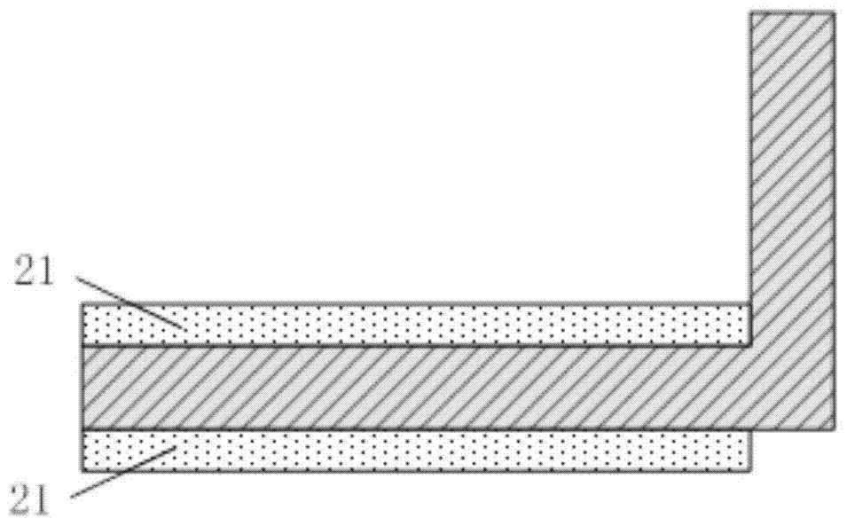
The invention discloses a backlight device, which comprises: a reflective sheet, a plastic frame in contact with the reflective sheet, and a light guide plate accommodated in the plastic frame, wherein the plastic frame and the reflective The side in contact with the sheet is the first side of the plastic frame, and the side of the plastic frame facing away from the reflective sheet is the second side of the plastic frame; the plastic frame includes at least one groove for fixing the light-emitting element, The plastic frame also includes a heat dissipation channel, the heat dissipation channel is arranged in at least one of the first surface and the second surface of the plastic frame, and the heat dissipation channel is located at a peripheral position of the groove. The invention passes through the heat dissipation channel of the plastic frame in the plastic frame to form air convection in the heat dissipation channel, which speeds up the heat energy exchange and improves the heat dissipation efficiency. The heat dissipation channel and the plastic frame are integrally formed without affecting the thickness of the backlight device. Advantages of low cost and easy thinning of the backlight device.

Description

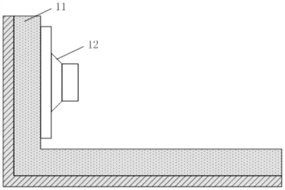
technical field [0001] The invention relates to the display field, in particular to a backlight device for a display. Background technique [0002] The backlight module is located under the liquid crystal display panel. The liquid crystal display panel is a passive light-emitting element. It does not emit light itself, but the light source provided by the light source located in the backlight module below it. The backlight module and the liquid crystal display panel are combined together A liquid crystal display module is formed, and the luminous effect of the backlight module will directly affect the display effect of the liquid crystal display module. [0003] Since there are multiple light sources in the backlight module, heat radiation will be generated when the light sources emit light. In the prior art, heat sinks are usually used to dissipate heat from the light sources in the backlight module. Referring to Fig. 1 (a), it is a schematic diagram of a backlight module ...

Claims


Application Information

Patent Timeline
Patent Type & Authority Patents(China)
IPC IPC(8): G02F1/13357F21S8/00F21V21/00F21V29/502
CPCF21S8/00F21V21/00G02F1/133603G02B6/0085G02B6/0091G02B6/0081
Inventor 陈江戴超李五洲
Owner WUHAN TIANMA MICRO ELECTRONICS CO LTD
Learn More