
Bonding structure, heater and bonding process

A bonding and process technology, applied in the bonding process field of bonding structures, can solve the problems of increased time-consuming bonding stations, large space occupation, long curing time, etc., to reduce production costs and improve production Efficiency, fast curing effect

Active Publication Date: 2018-04-24
GD MIDEA ENVIRONMENT APPLIANCES MFG +1
View PDF7 Cites 0 Cited by
  • Summary
  • Abstract
  • Description
  • Claims
  • Application Information

AI Technical Summary

Problems solved by technology

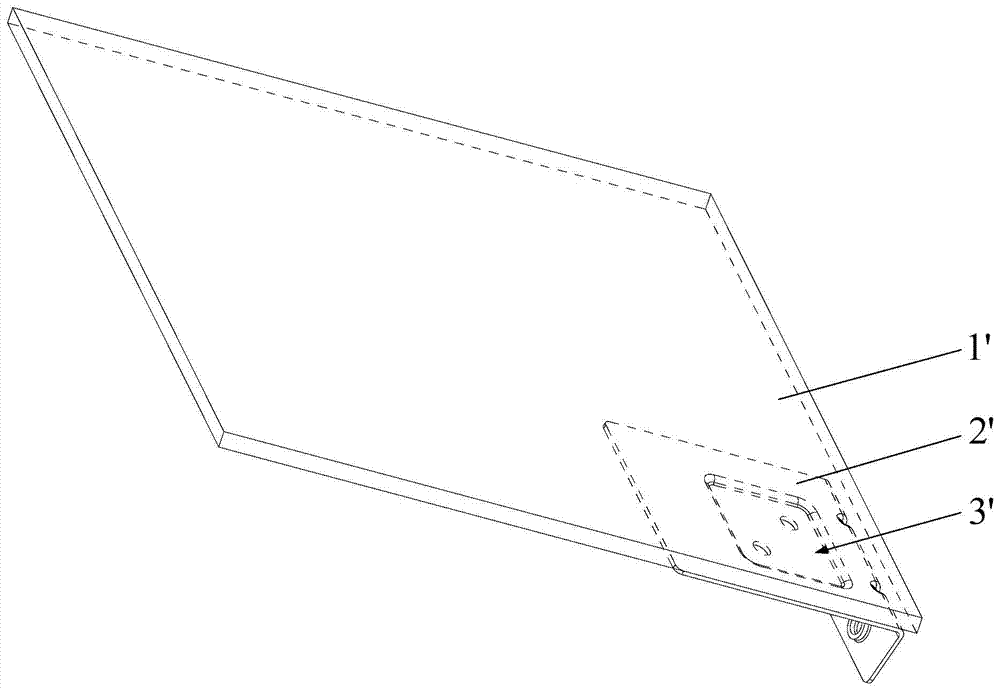
[0002] like figure 1 As shown, the metal sheet 2' of the existing heater is provided with a groove 3', and the high temperature resistant glass glue is injected into the groove 3' to bond the high temperature resistant glass plate 1' and the metal sheet 2' Fixed, however, in the existing production line of heaters, due to the long curing time of high temperature resistant glass glue, the time consumption of bonding stations increases, which greatly reduces the production efficiency of the whole product, which in turn leads to the cost increase; in order to solve this problem, the high-temperature-resistant glass plate 1' and the metal sheet 2' are usually bonded in advance in the prior art. Although this method improves the assembly line production efficiency of the product to a certain extent, the bonding The connected high-temperature-resistant glass plate 1' and the metal sheet 2' need to occupy a large space during the curing process of the high-temperature-resistant glass glue, which leads to certain limitations in the use of this method and is not easy to promote

Method used


Image

  • Bonding structure, heater and bonding process
  • Bonding structure, heater and bonding process
  • Bonding structure, heater and bonding process

Examples


Embodiment Construction

[0035] In order to understand the above-mentioned purpose, features and advantages of the present invention more clearly, the present invention will be further described in detail below in conjunction with the accompanying drawings and specific embodiments. It should be noted that, in the case of no conflict, the embodiments of the present application and the features in the embodiments can be combined with each other.

[0036] In the following description, many specific details are set forth in order to fully understand the present invention. However, the present invention can also be implemented in other ways different from those described here. Therefore, the protection scope of the present invention is not limited by the specific details disclosed below. EXAMPLE LIMITATIONS.

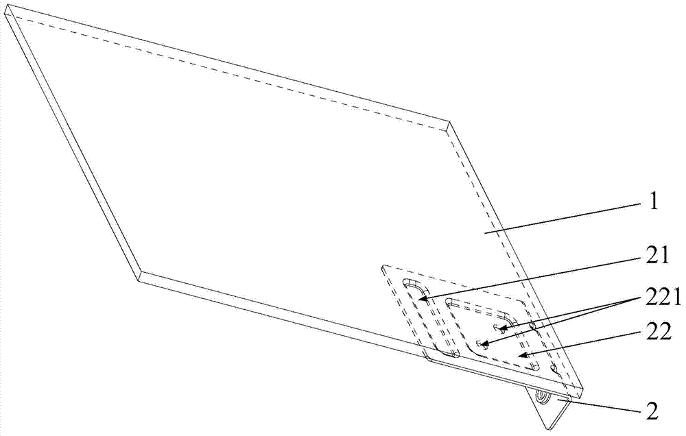
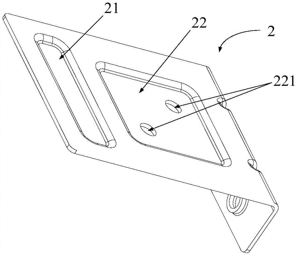
[0037] Refer below Figure 2 to Figure 5 The bonding structure according to some embodiments of the present invention is described.

[0038] Such as Figure 2 to Figure 5 As shown, the bonding str...


PUM


Abstract

The invention provides an adhesion structure, a heater and an adhesion process. The adhesion structure comprises a first plate, a second plate, a quickly-drying adhesive layer and a high-temperature-resistant adhesive layer. The second plate is provided with a first groove and a second groove, the quickly-drying adhesive layer is located in the first groove and enables the second plate and the first plate to fixedly adhere to each other, and the high-temperature-resistant adhesive layer is located in the second groove and enables the second plate and the first plate to fixedly adhere to each other. According to the adhesion structure, the quickly-drying adhesive layer rapidly fixes the first plate and the second plate, can meet the requirement for fixing strength between the first plate and the second plate in a flowing production process and enables the first plate and the second plate which adhere to each other through the quickly-drying adhesive layer to enter the flowing production process, and the high-temperature-resistant adhesive layer cures naturally in the following production process, so that on the premise of not influencing the use performance of the product, the time consumption of an adhesion station is lowered, the production efficiency of the complete product is improved, and the production cost of the product is lowered.

Description

technical field [0001] The present invention relates to the technical field of bonding technology for bonding structures, in particular, to a bonding structure, a heater with the bonding structure, and a bonding process for the bonding structure. Background technique [0002] Such as figure 1 As shown, the metal sheet 2' of the existing heater is provided with a groove 3', and the high temperature resistant glass glue is injected into the groove 3' to bond the high temperature resistant glass plate 1' and the metal sheet 2' Fixed, however, in the existing production line of heaters, due to the long curing time of high temperature resistant glass glue, the time consumption of bonding stations increases, which greatly reduces the production efficiency of the whole product, which in turn leads to the cost increase; in order to solve this problem, the high-temperature-resistant glass plate 1' and the metal sheet 2' are usually bonded in advance in the prior art. Although this m...

Claims


Application Information

Patent Timeline
Patent Type & Authority Patents(China)
IPC IPC(8): F24D19/00
Inventor 杨鑫陈金水
Owner GD MIDEA ENVIRONMENT APPLIANCES MFG
Learn More