Optical measuring equipment

A technology of optical measuring equipment and measuring devices, which is applied in the field of optical measurement, can solve the problems of low accuracy, high labor cost, and low efficiency, achieve stable and accurate data, solve the effects of large footprint, and eliminate interference factors

Active Publication Date: 2015-04-22
HANS LASER TECH IND GRP CO LTD
View PDF10 Cites 19 Cited by
  • Summary
  • Abstract
  • Description
  • Claims
  • Application Information

AI Technical Summary

Problems solved by technology

The traditional manual detection method can only be measured by naked eyes and rulers. It has high requirements on the quality of the staff and high labor cost, but the efficiency is very low, the error caused by man-made is relatively large, the accuracy is low, and the consistency of the data results is poor. Even contact with the workpiece during measurement may scratch, deform or distort the workpiece, resulting in the scrapping of the workpiece
[0003] In addition, the existing special testing equipment can only perform a single measurement. If it is necessary to measure multiple items of the workpiece, different testing equipment must be placed together, which is not only easily limited by the area of ​​the site, but also The efficiency and degree of automation are very low, which is far from meeting the production needs

Method used


Image

  • Optical measuring equipment
  • Optical measuring equipment
  • Optical measuring equipment

Examples


Embodiment Construction

[0031] In order to make the object, technical solution and advantages of the present invention clearer, the present invention will be further described in detail below in conjunction with the accompanying drawings and embodiments. It should be understood that the specific embodiments described here are only used to explain the present invention, not to limit the present invention.

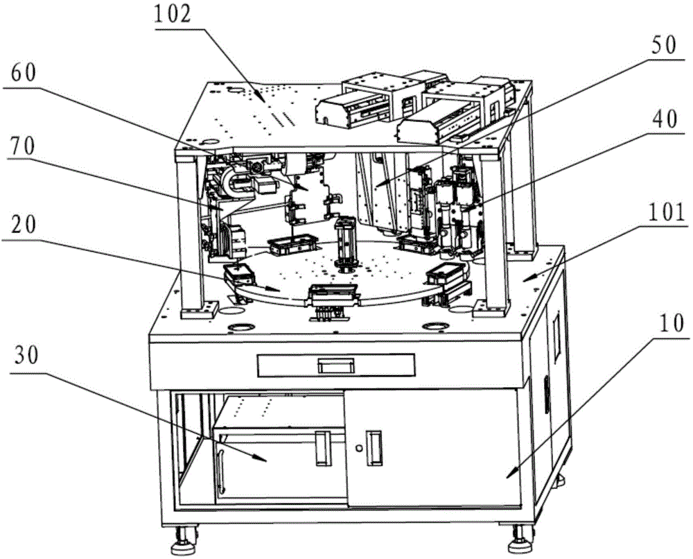
[0032] like figure 1 As shown, the embodiment of the present invention provides an optical measurement device, which includes a cabinet 10 , a positioning device 20 , a measurement system and an industrial control system 30 . in,

[0033] A workbench 101 is provided at the upper end of the cabinet 10, and a gantry structure frame 102 is provided on the workbench 101;

[0034] The positioning device 20 is arranged on the workbench 101, and is used to carry and fix the workpiece, and can drive the workpiece to move on the workbench 101;

[0035] The measuring system is installed on the gantry stru...


PUM


Abstract

The invention relates to optical measuring equipment. The optical measuring equipment comprises an equipment cabinet, a positioning device, a measuring system and a project control system, wherein a working table is arranged at the upper end of the equipment cabinet, and the working table is provided with a gantry structure frame; the positioning device is arranged on the working table, and the positioning device is used for bearing and fixing a workpiece and can drive the workpiece to move on the working table; the measuring system is arranged on the gantry structure frame and located above the positioning device, and is used for measuring the data of the inner length, the inner width, the outer length and the outer width of the workpiece as well as the width, the profile tolerance, the flatness, the parallelism, the height difference and the like of a specific face; the project control system is arranged in the equipment cabinet, and is used for controlling the positioning device and the measuring system, and calculating and analyzing the data fed back by the measuring system. The optical measuring equipment achieves multi-project automatic detection, and has the advantages of being high in precision, few in man-made interference factors, low in cost and high in efficiency.

Description

technical field [0001] The invention relates to the technical field of optical measurement, in particular to a non-contact, multi-item automatic detection optical measurement device. Background technique [0002] In the production process of mobile phones and other electronic products and their accessories, it is necessary to strictly test the inner length, inner width, outer length, outer width, flatness, contour and other items of the workpiece. The traditional manual detection method can only be measured by naked eyes and rulers. It has high requirements for the quality of the staff and high labor cost, but the efficiency is very low, the error caused by man-made is relatively large, the accuracy is low, and the consistency of the data results is poor. Even contact with the workpiece during measurement may scratch, deform or distort the workpiece, resulting in the scrapping of the workpiece. [0003] In addition, the existing special testing equipment can only perform a ...

Claims


Application Information

Patent Timeline
Patent Type & Authority Applications(China)
IPC IPC(8): G01B11/02G01B11/06G01B11/24G01B11/26G01B11/30
Inventor 吴顺柏罗锐刘朋飞杜荣钦刘建华王刚高泽润范小卫郭明森仝敬烁尹建刚高云峰
Owner HANS LASER TECH IND GRP CO LTD
Why Eureka
Try Eureka