Robot precision compensation method for variable-parameter error recognition

A technology of precision compensation and robotics, which is applied in the direction of instruments, measuring devices, surveying and navigation, etc., can solve the problems of inability to accurately describe the error model, failure to consider the influence of flexibility, and inability to realize the compensation of the absolute positioning accuracy of the robot.

Active Publication Date: 2015-04-22
江苏航鼎智能装备有限公司
View PDF6 Cites 40 Cited by
  • Summary
  • Abstract
  • Description
  • Claims
  • Application Information

AI Technical Summary

Problems solved by technology

[0005] 1) The robot is regarded as a rigid body, and the influence of flexibility on the robot is not considered;
[0006] 2) Only the errors of parameter items a and d are considered, but the actual impact on positioning accuracy is not only determined by the above two parameters, but also affected by α and θ;
[0007] 3) The test results show that the effect of the robot after calibration is still not ideal
[0010] 2) Use grids to divide the working space of the robot and use the interpolation method to process the errors. The consideration of the error weight in this method is mainly to estimate the error distribution in the space, but it cannot accurately describe its error model, so it can improve The accuracy is still limited;
[0011] In this method, the compensation of the absolute positioning accuracy of the robot under different attitudes cannot be realized.

Method used


Image

  • Robot precision compensation method for variable-parameter error recognition
  • Robot precision compensation method for variable-parameter error recognition
  • Robot precision compensation method for variable-parameter error recognition

Examples


Embodiment Construction

[0069] The present invention will be further described below in conjunction with the accompanying drawings.

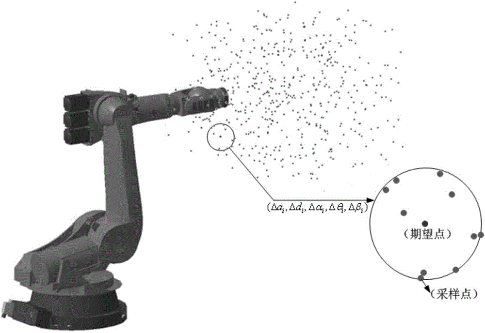
[0070] A robot accuracy compensation method for variable parameter error identification, such as figure 1 shown, including the following steps:

[0071] The first step is to fix the laser tracker on the ground, and use the laser tracker to establish the coordinate system of the robot base and the flange:

[0072] 1) Put the spherical reflector SMR of the laser tracker on the plane of the robot base, move a certain distance along the plane of the base, use the continuous measurement method of the laser tracker to collect a series of points on the distance, and use the built-in The software's fitting plane command and offset command (the offset distance is the SMR radius) fit a plane, which is the robot base plane Baseplane;

[0073] 2) Install an SMR seat on the flange plane of the robot, fix the SMR on the SMR seat, then lock the A2 axis to the A6 axis of the robot, ...


PUM


Abstract

The invention discloses a robot precision compensation method for variable-parameter error recognition and belongs to the technical field of robot inverse calibration. A variable-parameter error module is provided, errors of pose points of a robot in different spaces are sampled through a laser tracker, a plurality of points which are closest to an expected pose point are sought in the near area range according to the space where the expected pose point is located, and an improved Levenberg-Marquardt damp iterative least square method algorithm is used for solving the global convergent solution of the parameter error corresponding to the expected pose point, and therefore the practical parameter of the expected pose point is solved. The pose point at which the robot should arrive practically is solved through the practical parameter of the expected pose point and through inverse kinematics of the expected pose point, and the absolute positioning precision compensation of the robot at the pose point is achieved. The robot precision compensation method can obviously improve the absolute positioning precision of the robot and can be applied to the field where the requirement for robot precision is high.

Description

technical field [0001] The invention relates to a robot precision compensation method for variable parameter error identification, belonging to the technical field of robot inverse calibration. Background technique [0002] In recent years, robotics has attracted extensive attention from scholars at home and abroad. Among them, the repetitive positioning accuracy and absolute positioning accuracy of the robot are important indicators of the robot. At present, the repeated positioning accuracy of robots can reach a high level, but the absolute positioning accuracy is relatively low. For example, the repeated positioning accuracy of KUKA-KR210 can reach 0.06mm, and the absolute positioning accuracy is affected by factors such as manufacturing, assembly and flexibility. It can only reach 1-3mm, and it is difficult to meet the fields that require high robot precision (such as in the aviation field, requiring it to be within ±0.5mm). [0003] In order to meet this requirement, ...

Claims


Application Information

Patent Timeline
Patent Type & Authority Applications(China)
IPC IPC(8): G01B21/00G01C21/00G01C25/00
CPCG01C21/20G01C25/00
Inventor 田威廖文和洪鹏曾远帆梅东棋李冬磊
Owner 江苏航鼎智能装备有限公司
Why Eureka
Try Eureka