Method for Determining Load Threshold of Railway Subgrade Soil Deformation State under Static Load

A railway subgrade and soil deformation technology, applied in the direction of applying stable tension/pressure to test the strength of materials, can solve the problems of large threshold fluctuation range, long time, large randomness and subjectivity, etc., to ensure accuracy and reliability The effect of high stability, reduced time cost, good mechanical response and deformation law

Active Publication Date: 2017-06-06
SOUTHWEST JIAOTONG UNIV
View PDF9 Cites 0 Cited by
  • Summary
  • Abstract
  • Description
  • Claims
  • Application Information

AI Technical Summary

Problems solved by technology

There are the following deficiencies: 1) Due to the limitation of the small size of creep geotechnical test specimens and the accuracy of sensor testing, it is difficult to obtain 10 -6 ~10 -4 Mechanical response data under micro-strain conditions; 2) Determining the load thresholds of the two deformation states of slow stability and slow failure of the soil lacks a clear and quantitative criterion, which is largely arbitrary and subjective, and the threshold fluctuation range is too large; 3) The creep test process takes too long to be widely used in large-scale engineering construction

Method used


Image

  • Method for Determining Load Threshold of Railway Subgrade Soil Deformation State under Static Load
  • Method for Determining Load Threshold of Railway Subgrade Soil Deformation State under Static Load
  • Method for Determining Load Threshold of Railway Subgrade Soil Deformation State under Static Load

Examples


specific Embodiment approach

[0036] A specific embodiment of the present invention is: a method for measuring the load threshold value of the soil deformation state of the railway embankment under a constant static load, comprising the following steps:

[0037] A. Test preparation

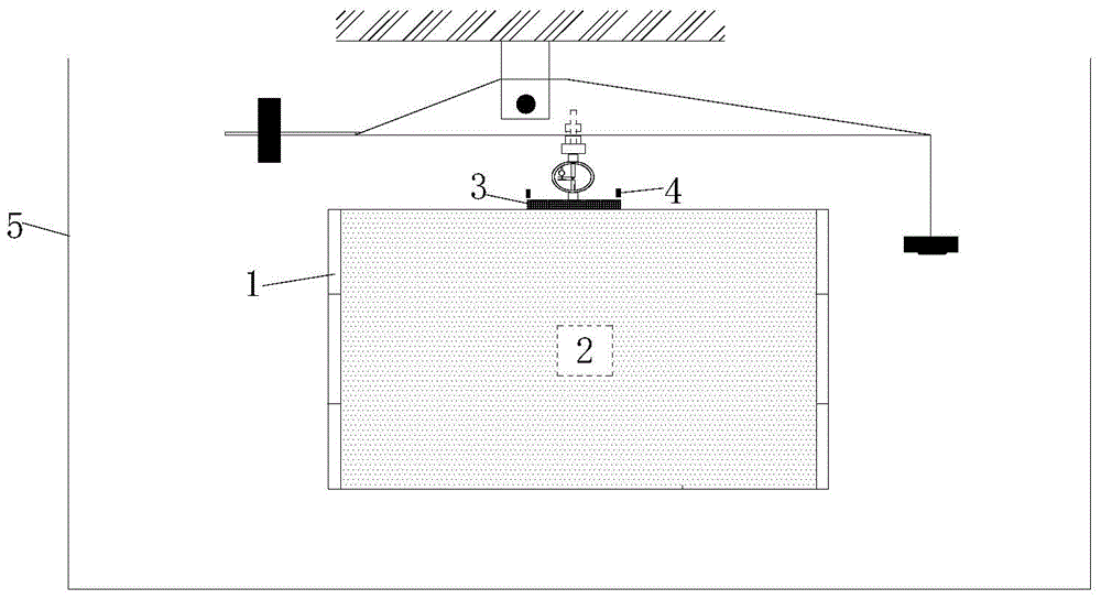
[0038] A1. Model box construction: Build a rigid model side wall on a rigid foundation to form a model box 1 with a length, width and height of 150cm, 150cm and 90cm respectively;

[0039] A2. Model filling: Fill the railway foundation soil samples used in the test in layers according to the predetermined degree of compaction in the model box to form the filling model 2. The thickness of each layer of filling is 20-25cm, and the total height of the filling model 90cm;

[0040] A3. Placement of the loading plate: place a circular rigid loading plate 3 with a diameter of 30 cm at the center of the upper surface of the fill model 2;

[0041] A4. Displacement sensor layout: three displacement sensors 4 are uniformly arranged on ...


PUM


Abstract

A method for measuring the load threshold value of the deformation state of railway foundation soil under static load, the operation steps are: construct a fill model in a model box formed by rigid side walls, press the limit bearing capacity of the fill model by a circular rigid loading plate Static loads are applied in stages with different proportional coefficients λi; the plastic deformation rate vi(t) of the soil at different moments t during the loading process is measured and calculated by the displacement sensor, and its effective data points are taken, according to the negative power function v(t)=At ‑α fitting; get the power exponent αi value corresponding to the load proportional coefficient λi, and fit it according to the cubic polynomial to obtain the α~λ curve, and the λΙ and λII corresponding to the two curvature maximum points of the α~λ curve The load pΙ=λΙσf and pII=λIIσf are used as the load threshold of the soil deformation state. pΙ and pII can provide experimental basis for the design and optimization of high-speed railway ballastless / ballasted track subgrade, evaluation of deformation state and regulation principles. This method has the characteristics of short test time and clear judgment criteria, and the obtained load threshold is more accurate and reliable.

Description

technical field [0001] The invention relates to a method for measuring the load threshold value of the deformation state of railway foundation soil, and belongs to the technical field of soil engineering. Background technique [0002] The post-construction settlement of the railway subgrade will seriously affect the geometric smoothness of the track structure, and then affect the smoothness and safety of driving. The main reason for the subsidence of the railway subgrade is that the foundation is deformed by the long-term action of the self-weight of the superstructure such as the embankment. For ballasted track railways, in the long-term operation process, the smoothness of the track structure can be maintained by maintenance methods such as lifting, ballasting, and vibration. Therefore, certain deformation of the foundation is allowed. However, in order to ensure the efficient operation of the railway and the effective utilization of the line, the foundation of the ballas...

Claims


Application Information

Patent Timeline
Patent Type & Authority Patents(China)
IPC IPC(8): G01N3/08
Inventor 罗强熊勇张良蒋良潍刘钢朱江江孟伟超侯振斌邹亮明叶庆志
Owner SOUTHWEST JIAOTONG UNIV
Why Eureka
Try Eureka