Cascaded automatic generation control method for hydropower station group

A technology for automatic power generation control and cascade hydropower station groups, applied to electrical components, circuit devices, AC network circuits, etc., can solve problems such as dimensionality barriers, failure to meet real-time requirements, and failure to play the anti-regulation role of downstream hydropower stations. The effect of enhancing practicality and improving the efficiency of real-time load distribution

Active Publication Date: 2015-04-22
HUAZHONG UNIV OF SCI & TECH
View PDF5 Cites 9 Cited by
  • Summary
  • Abstract
  • Description
  • Claims
  • Application Information

AI Technical Summary

Problems solved by technology

However, the above method has the following technical defects: (1) The boundary conditions of the cascade AGC model, such as the total load of the cascade, the water level of the upper reservoir, and the inflow flow, etc., small real-time changes will cause the load distributed between the cascade hydropower stations to change drastically in continuous time , resulting in a large-scale transfer of loads between plants; (2) Although the use of equal water consumption distribution methods can solve the problems in (1), in practical applications, this method will cause the upstream and downstream hydropower stations to go out of the storage and storage due to the arrival time of the water flow. It cannot be synchronized, and the anti-regulation effect of the downstream hydropower station cannot be brought into play, resulting in the conflict between cascade peak regulation and frequency regulation operation; (3) Static

Method used


Image

  • Cascaded automatic generation control method for hydropower station group
  • Cascaded automatic generation control method for hydropower station group
  • Cascaded automatic generation control method for hydropower station group

Examples


Embodiment Construction

[0026] In order to make the object, technical solution and advantages of the present invention clearer, the present invention will be further described in detail below in conjunction with the accompanying drawings and embodiments. It should be understood that the specific embodiments described here are only used to explain the present invention, not to limit the present invention. In addition, the technical features involved in the various embodiments of the present invention described below can be combined with each other as long as they do not constitute a conflict with each other.

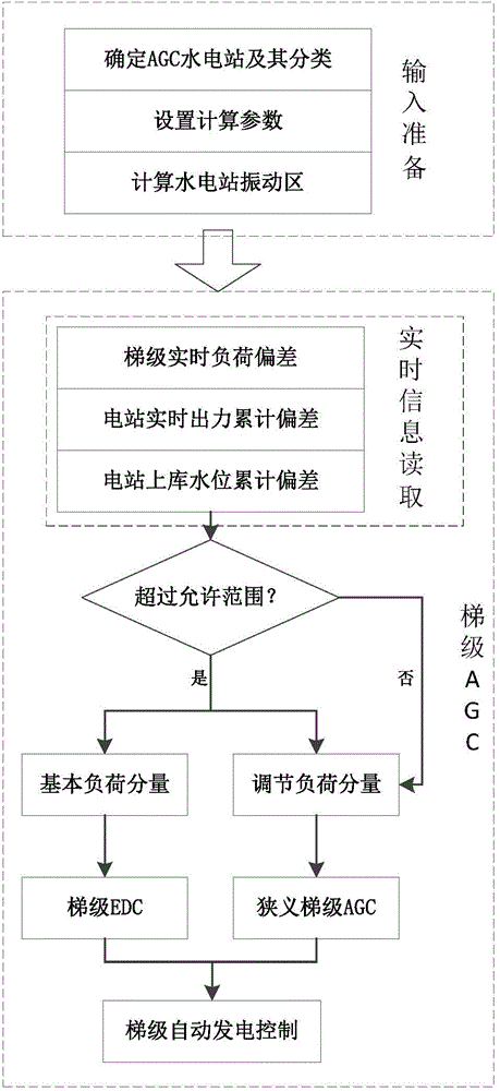
[0027] figure 1 Shown is the flow chart of the automatic generation control method of cascade hydropower station group of the present invention, specifically comprises the following steps:

[0028] Step 1 Select multiple hydropower stations participating in the cascade AGC, classify them according to their regulation performance, and use the traversal search method to determine the upstream and...


PUM


Abstract

The invention discloses a cascaded automatic generation control method for a hydropower station group and belongs to the technical field of hydraulic and electric engineering. The automatic generation control method comprises the following steps: selecting hydropower stations and carrying out classification and topological relation treatment on the hydropower stations; setting related initial conditions; determining a vibration zone of the hydropower stations and output correction modes; decomposing a cascaded real-time load to obtain a basic load (EDC) component and an adjusting load (ACE) component, and judging whether a cascaded EDC model is invoked or not according to real-time information deviation; constructing the cascaded EDC model to distribute the EDC component; constructing a narrow-sense cascaded AGC model to distribute the AGE component; and obtaining real-time set outputs of the cascaded hydropower stations. According to the method disclosed by the invention, the counter adjusting effect of a daily adjustment hydropower station is fully exerted to coordinate cascaded pitch peak and frequency modulation operation. The cascaded load EDC component and the ACE component are respectively distributed, so that the problem of massive load transfer is effectively avoided, and the economical benefit and the safety of the cascaded hydropower stations are ensured. Therefore, the engineering practicality of the method disclosed by the invention is further enhanced.

Description

technical field [0001] The invention belongs to the technical field of water conservancy and electric power, and more specifically relates to an automatic power generation control method for cascade hydropower station groups. Background technique [0002] The purpose of cascade automatic generation control (AGC) is to safely and economically distribute the real-time load of the power grid to each hydropower station in the cascade, which is similar to the cascade short-term power generation optimization dispatch task. Therefore, in the prior art, the cascade AGC mathematical model is usually established by referring to the cascade short-term optimal scheduling model, but the calculation period is shortened to ensure the real-time requirements of the cascade AGC. However, the above method has the following technical defects: (1) The boundary conditions of the cascade AGC model, such as the total load of the cascade, the water level of the upper reservoir, and the inflow flow, ...

Claims


Application Information

Patent Timeline
IPC IPC(8): H02J3/46
CPCH02J3/382H02J3/46
Inventor 伍永刚刘兴龙肖胜贤
Owner HUAZHONG UNIV OF SCI & TECH
Why Eureka
Try Eureka