Power generating device

A technology for power generation devices and generators, which is applied to electromechanical devices, electric components, electrical components, etc., can solve the problems of difficult assembly of power generation devices, low working efficiency of generators, poor linearity of magnetic field distribution, etc., so as to improve uniformity and power generation efficiency. , Improve the assembly production efficiency, the effect of small transmission vibration

Inactive Publication Date: 2015-04-22
CHONGQING ZHIREN ELECTRIC EQUIP
View PDF6 Cites 6 Cited by
  • Summary
  • Abstract
  • Description
  • Claims
  • Application Information

AI Technical Summary

Problems solved by technology

[0006] In view of this, the object of the present invention is to provide a power generation device to solve the problems of difficulty in assembling the power generation device, low working efficiency of the generator, poor linearity of the magnetic field distribution, and easy damage to the rotor shaft.

Method used


Image

  • Power generating device
  • Power generating device
  • Power generating device

Examples


Embodiment Construction

[0029] The present invention will be further described below in conjunction with the accompanying drawings and embodiments.

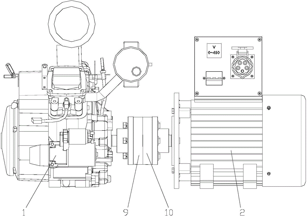
[0030] As shown in the figure, the power generation device of this embodiment includes an engine 1 and a generator 2. The generator includes a rotor shaft 3, an iron core 4 and a permanent magnet 5. The iron core is formed by overlapping and combining several punched pieces. The middle part of the sheet is provided with a shaft hole 6 matching with the rotor shaft, and the punching sheet is also provided with two groups of rectangular permanent magnet mounting holes 7 arranged axisymmetrically, and each group of permanent magnet mounting holes includes two permanent magnet mounting holes arranged in a figure-eight shape. holes, and the nearest two rectangular corners of the two permanent magnet mounting holes in each group are provided with communication grooves 8, and the permanent magnets are inserted in the permanent magnet mounting holes;

[0031] T...


PUM


Abstract

The invention discloses a power generating device. The power generating device comprises an engine and a generator. An output shaft of the engine is connected with a rotor shaft of the generator through a flexible coupling. The generator comprises the rotor shaft, iron cores and permanent magnets. The iron cores are composed of multiple stampings in an overlapping mode. An axle hole and mounting holes of the permanent magnets are arranged in the central sections of the stampings. The permanent magnets can be directly inserted into the iron cores on the rotor shaft composed of the stampings and therefore the quick and convenient installation can be achieved. More of the corner magnetic line of force of the permanent magnets can pass through the iron cores in a more even manner through communicated grooves. The boundary lines of the adjacent magnetic fields can be made clearer due to heat emission holes and concave grooves. A better linear distribution of the magnetic fields can be achieved, harmonic waves losess can be reduced and the working efficiency of the engine can be improved. Meanwhile, self-adaptive adjustment is achieved by flexible transmission ring segments and the flexible transmission ring segments are capable of compensating the errors in manufacturing, assembling and transmitting. The transmission vibration is low and the adaptability is high. At the same time, the manufacturing precision and the assembling difficulty are lowered, the working efficiency in assembling the power generating device is improved and the damage, caused by assembling errors, to the engine and an electric motor is avoided.

Description

technical field [0001] The invention relates to a power generating equipment, in particular to a combined power generating device. Background technique [0002] The combined power generation device is composed of two parts, the engine and the generator. The generator is composed of a rotor and a stator, and the rotor includes components such as a rotor shaft, an iron core, and a magnetic pole. The iron core of the rotor is generally composed of overlapping punched sheets of high magnetic permeability materials. The structure of the punched sheets directly affects the efficiency, life, performance, and assembly and production efficiency of the generator. [0003] For example, the existing power generator with a power of 6Kw adopts a magnetic tile structure for its power generation device. During installation, the magnetic tile is fixed on the cylindrical iron core composed of punched pieces through screws. The installation takes a long time and the work efficiency is low. At...

Claims


Application Information

Patent Timeline
Patent Type & Authority Applications(China)
IPC IPC(8): H02K1/27H02K1/32H02K7/00H02K7/18
Inventor 李曦杨均赵强
Owner CHONGQING ZHIREN ELECTRIC EQUIP
Why Eureka
Try Eureka