
Intervertebral foramen mirror

A technology of intervertebral foramina mirror and mirror tube, which is applied in the field of intervertebral foramina mirror, can solve the problems of low work efficiency, small instrument size, and low strength, and achieve the effects of shortening operation time, simple operation, and improving work efficiency

Inactive Publication Date: 2015-04-29
吴雨
View PDF10 Cites 7 Cited by
  • Summary
  • Abstract
  • Description
  • Claims
  • Application Information

AI Technical Summary

Problems solved by technology

[0004] However, the instrument channel of the currently used intervertebral foramina mirror is a closed circular channel, and the surgical instruments need to extend into the lesion from the instrument channel, so the size of the instrument must be smaller than the size of the instrument channel, so that it can be used under the intervertebral foramina mirror. The size of the equipment is very small, not only the work efficiency is low, but also the strength is low and it is easy to damage
In addition, the channel in the main structure of the intervertebral foramina mirror is also a closed circular channel. When inserting surgical instruments, it is not easy to align the front end of the instrument with the small hole, making it inconvenient to insert the surgical instrument.

Method used


Image

  • Intervertebral foramen mirror
  • Intervertebral foramen mirror
  • Intervertebral foramen mirror

Examples


Embodiment Construction

[0021] Below in conjunction with accompanying drawing and embodiment, further elaborate the present invention. In the following detailed description, certain exemplary embodiments of the invention are described by way of illustration only. Needless to say, those skilled in the art would realize that the described embodiments can be modified in various different ways, all without departing from the spirit and scope of the present invention. Accordingly, the drawings and description are illustrative in nature and not intended to limit the scope of the claims.

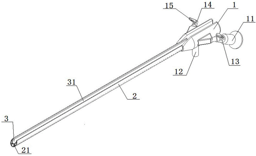
[0022] Please refer to figure 1 As shown, the preferred embodiment of the intervertebral foramina mirror of the present invention includes: a main body structure 1 and a working mirror tube 2 connected to one end of the main body structure 1 .

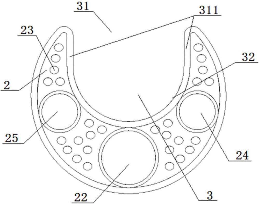
[0023] The working mirror tube 2 and the main body structure 1 are provided with an instrument channel 3 that runs through both ends of the entire intervertebral foramen mirror....


PUM


Abstract

The invention discloses an intervertebral foramen mirror which comprises a main structure and a working mirror tube connected with one end of the main structure. An instrument passage penetrating two ends of the intervertebral foramen mirror is arranged on the working mirror tube and the main structure, and an opening is formed in the side wall of the instrument passage. An operating instrument inserting mode is added, and a knife head portion for cutting tissue can be made in larger size, so that working efficiency and strength of an operating instrument are improved, operating operation is enabled to be simpler and more efficient, and the operating instrument is durable.

Description

technical field [0001] The invention relates to a medical device, in particular to an intervertebral foramina mirror. Background technique [0002] The purpose of the transforaminal minimally invasive spinal technique is to establish a working channel from the side or rear of the patient's body to enter the intervertebral foramen, and to completely remove the protruding or prolapsed spinal cord outside the safe triangle of the intervertebral foramen and the fibrous annulus of the intervertebral disc. Nuclei and hyperplastic bone to relieve the pressure on the nerve root, relieve the obstruction of lateral recess circulation caused by disc herniation, nerve root edema and aseptic inflammation again, resulting in recurrence of clinical symptoms. The operation method is a spinal minimally invasive surgery system composed of a specially designed intervertebral foramenoscope, corresponding supporting spinal minimally invasive surgical instruments, imaging and image processing sys...

Claims


Application Information

Patent Timeline
IPC IPC(8): A61B1/317A61B1/04A61B1/07A61B1/018
CPCA61B1/317A61B1/012A61B17/320016
Inventor 吴雨
Owner 吴雨
Learn More