Electromagnetic stirrer

An electromagnetic stirrer and high magnetic technology, applied in chemical instruments and methods, dissolution, mixers, etc., can solve the problems of poor performance stability of electromagnetic stirrer, low coil cooling efficiency, interference in non-working areas, etc., to achieve Reduce processing difficulty and production cost, wide application range, improve performance and reliability

Inactive Publication Date: 2015-04-29
DANYANG ZHISHENG ALLOY
View PDF8 Cites 0 Cited by
  • Summary
  • Abstract
  • Description
  • Claims
  • Application Information

AI Technical Summary

Problems solved by technology

For example, application number 201110450015.4 discloses a multifunctional electromagnetic stirrer, which includes six layers of horizontally arranged annular iron cores, six vertically arranged rack iron cores, and thirty-six identical electromagnetic coil windings. The six-layer annular iron core The layers are independent of each other, aligned up and down and separated by a certain distance, and the inner wall of each layer of annular iron core has six salient poles, and the six rack iron cores are evenly distributed on the outer wall of the annular iron core, and each tooth The bar core has five salient poles, and the salient poles of the rack core are inserted into the upper and lower intervals of the annular iron core, and the salient poles of each rack core are on the same circumference as the salient poles of the six-layer annular iron core position, the top surface of the salient poles of each rack core is inserted into the inner wall between the salient poles of the annular iron core, and the thirty-six electromagnetic coil windings are respectively set on each salient pole of the annular iron core, and are powered by a variable frequency power supply Supplying three-phase low-frequency alternating current, the invention has simple structure, small size, small magnetic flux leakage, and high work efficiency, but the cooling efficiency of the coil in this invention is not high, which makes the performance stability of the electromagnetic stirrer poor, and long-term work will reduce the sensitivity of the operation, and There is no shielding layer, which will cause unnecessary interference to non-working areas, and the scope of application is limited

Method used


Image

  • Electromagnetic stirrer
  • Electromagnetic stirrer
  • Electromagnetic stirrer

Examples


Embodiment Construction

[0014] In order to make the technical means, creative features, goals and effects achieved by the present invention easy to understand, the present invention will be further described below in conjunction with specific embodiments.

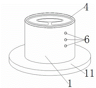
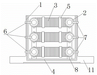
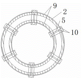
[0015] Such as figure 1 and figure 2 As shown, a kind of electromagnetic stirrer comprises shell 1, is arranged on the annular hollow copper tube 2 in described shell, the coil 3 wound on the described copper tube and is arranged on the shielding between described shell and copper tube Layer 4, three layers of the same copper pipe 2 are arranged in the vertical direction, and a high magnetic ring 5 is provided at the joint of the copper pipe 2, and the high magnetic ring 5 is arranged between two coils 3, and the copper pipe 2. The thickness is 4-8mm. The outer side of the copper pipe 2 is provided with a water inlet 6 and a water outlet 7. The horizontally placed copper pipe 2 is provided with the same three layers in the vertical direction. Th...


PUM

PropertyMeasurementUnit
thicknessaaaaaaaaaa

Abstract

The invention discloses an electromagnetic stirrer and relates to the field of metallurgical equipment. The electromagnetic stirrer comprises a shell, annular hollow core copper pipes arranged in the shell, coils wound on the copper pipes, and a shielding layer arranged between the shell and the copper pipe, wherein a high magnet ring is arranged on the connection position of the copper pipe and is arranged between two sections of coils; the thickness of the copper pipe is in the range from 4 to 8mm; the outer side of the copper pipe is provided with a water inlet and a water outlet; three layers of same horizontally-positioned copper pipe are arranged in the vertical direction; an annular insulation spacer is arranged between the two adjacent copper pipes; the annular hollow core copper pipe is cooled by water introduced to the annular hollow core copper pipe so that the copper pipes and the coils are quickened in heat dissipation, the performance reliability of the stirrer is improved, high magnetic permeability and sealing at the connection position can be ensured by the high magnet ring, processing difficulty and production cost of the copper pipe can be reduced, the insulation spacer can support the copper pipe and prevent interference between the adjacent copper pipes, and a non-working region can be prevented from being subjected to electromagnetic interference by the shielding layer, and thus the electromagnetic stirrer is wide in application scope.

Description

technical field [0001] The invention belongs to the field of metallurgical equipment, in particular to an electromagnetic stirrer. Background technique [0002] The electromagnetic stirrer uses the electromagnetic force induced in the liquid phase cavity of the billet to strengthen the movement of the molten metal and stir the molten metal to make it evenly heated. The electromagnetic stirrer has become one of the standard equipment in modern metallurgical production. For example, application number 201110450015.4 discloses a multifunctional electromagnetic stirrer, which includes six layers of horizontally arranged annular iron cores, six vertically arranged rack iron cores, and thirty-six identical electromagnetic coil windings. The six-layer annular iron core The layers are independent of each other, aligned up and down and separated by a certain distance, and the inner wall of each layer of annular iron core has six salient poles, and the six rack iron cores are evenly d...

Claims


Application Information

Patent Timeline
Patent Type & Authority Applications(China)
IPC IPC(8): B01F13/08
Inventor 王良玉张坚刘浩方
Owner DANYANG ZHISHENG ALLOY
Why Eureka
Try Eureka