Aluminum alloy semi-continuous cast electromagnetic stirring device and method

An electromagnetic stirring and semi-continuous technology, applied in the field of foundry metallurgy, can solve the problems of long flow formation time, inability to adapt to the solidification speed of semi-continuous casting, uncontrollable flow mode, etc., and achieve the effect of homogenization and refinement of the structure

Inactive Publication Date: 2015-04-29
SHANGHAI DIANJI UNIV
View PDF5 Cites 6 Cited by
  • Summary
  • Abstract
  • Description
  • Claims
  • Application Information

AI Technical Summary

Problems solved by technology

Obviously, this method cannot produce effects quickly, and the flow method formed is uncontrollable. The movement of part of the melt is not driven by electromagnetic force, but driven by the drag force caused by the viscosity of the melt, so this method is not suitable for application When it comes to the homogenization of the melt composition and the refinement of the structure in the semi-continuous casting process, it takes a long time to flow and form, and cannot adapt to the high-speed solidification speed of the semi-continuous casting

Method used


Image

  • Aluminum alloy semi-continuous cast electromagnetic stirring device and method
  • Aluminum alloy semi-continuous cast electromagnetic stirring device and method

Examples


Embodiment 1

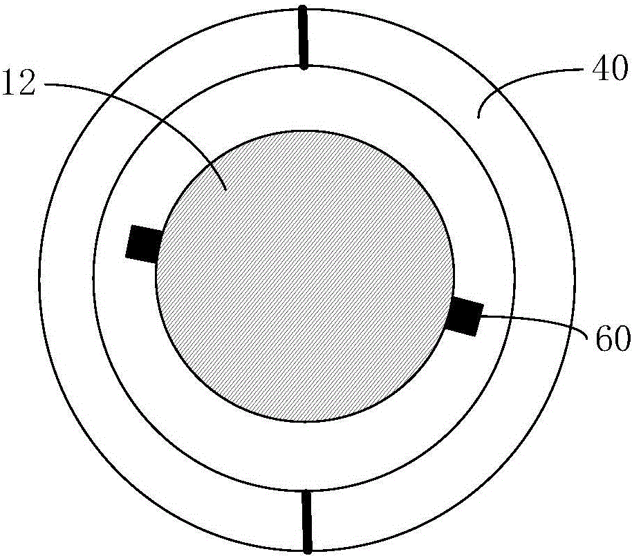
[0028] For round ingots with small diameter (eg φ=180mm), please refer to figure 2 , using the design of half-type permanent magnets, the sliding electrodes 60 are two or four, arranged in pairs, and the current adopts 10A, pulsed continuous current. For A356 alloy, the grain size can be controlled below 50 microns.

Embodiment 2

[0030] For a round ingot with a large diameter (eg, φ=500mm), a half-type permanent magnet design is adopted, and the sliding electrodes 60 are four or six, arranged in pairs, and the current adopts 30A, a pulsed continuous current. For 6016 alloy, the grain size can be controlled below 100 microns.

Embodiment 3

[0032] For large slab ingots (for example, the size is 1300mm×620mm), use the opposed multi-pole magnet design, design 4-6 pairs of sliding electrodes 60 on the long side, and design 2 pairs of electrodes on the short side, the current adopts 50A, pulse type and The electric current whose polarity is periodically reversed is used to balance the temperature of the large-section melt 11 and the distribution of alloying elements. The grain size of 6061 alloy can be controlled below 300 microns.

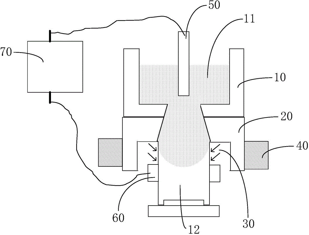
[0033] In summary, the present invention provides an aluminum alloy semi-continuous casting electromagnetic stirring device and method, the device includes a launder 10 for carrying a melt 11, a crystallizer 20 is provided under the launder 10, and the The lower outlet of the crystallizer 20 is provided with a cooling water injection zone 30, the outside of the crystallizer 20 is provided with permanent magnets 40 in pairs, the melt 11 is inserted with a graphite electrode 50, and the co...


PUM

PropertyMeasurementUnit
sizeaaaaaaaaaa
sizeaaaaaaaaaa

Abstract

The invention relates to an aluminum alloy semi-continuous cast electromagnetic stirring device and method. The aluminum alloy semi-continuous cast electromagnetic stirring device comprises a launder used for holding melt, a crystallizer is arranged blow the launder, a cooling water spray zone is arranged at the lower outlet of the crystallizer, permanent magnets are arranged at the outer side of the crystallizer in pairs, a graphite electrode is inserted in the melt, a plurality of sliding electrodes are arranged below the cooling water spray zone, and the graphite electrode and sliding electrodes are respectively connected with two electrodes of a pulse direct current power supply. The aluminum alloy semi-continuous cast electromagnetic stirring device uses the principle that current undergoes ampere force in a magnetic field and combines direct current with permanent magnets, the flow modes and flow intensities of different melts in the crystallizer region are designed according to sizes, shapes and material components of aluminum ingots, and segregation behaviors of alloying elements and growth patterns of dendritic crystals are controlled to realize microstructure homogenization and refining.

Description

technical field [0001] The invention relates to the field of casting metallurgy, in particular to an aluminum alloy semi-continuous casting electromagnetic stirring device and method. Background technique [0002] At present, there are two types of aluminum melt stirring technology used in industry: mechanical stirring and non-contact stirring. Non-contact stirring is mainly designed based on the principle of magnetic field, which includes two process methods: rotating electromagnetic field type and permanent magnet type. [0003] Among them, using the electromagnetic force induced by the rotating electromagnetic field in the melt to strongly stir the melt has become a common method for homogenizing the melt and refining the grain structure in the process of melting and semi-continuous casting of aluminum alloys. industrial applications. However, due to the skin effect of the rotating electromagnetic field and the limitation of installation (the area that needs to be stirr...

Claims


Application Information

Patent Timeline
Patent Type & Authority Applications(China)
IPC IPC(8): B22D11/115
CPCB22D11/115
Inventor 孙会
Owner SHANGHAI DIANJI UNIV
Why Eureka
Try Eureka