
Coat as well as method and device for coating

a technology of coating and method, applied in the direction of solid-state diffusion coating, plasma technique, transportation and packaging, etc., can solve the problems of complex apparatus used for high-temperature plasma generation, high energy consumption of plasma spraying, and inability to cost-effectively coat substrates

Inactive Publication Date: 2014-01-23
ECKART GMBH & CO KG +1
View PDF5 Cites 30 Cited by
  • Summary
  • Abstract
  • Description
  • Claims
  • Application Information

AI Technical Summary

Benefits of technology

This patent aims to provide a method for applying a coat onto a substrate with reduced reaction energy, which allows for a smoother coating process with materials that have higher melting temperatures. The technical effect is the ability to create a flawless coating without any defects or flaws.

Problems solved by technology

Accordingly, plasma spraying is very demanding in terms of energy, where a cost-effective coating of substrate is often not possible.
In addition, complex apparatus must be used for generation of the high temperatures.
Due to the high temperatures, temperature-sensitive and / or very thin substrates, like polymer films and / or paper, cannot be coated.
Due to the high thermal energy, damages are caused to such substrates.
Additionally, it is disadvantageous that the particles used are subject to a high thermal load during plasma spraying, where the particles can oxidize at least partially, for example, when using metallic particles.
For example, it is disadvantageous if metallic layers are intended to be deposited for use, for example, for conductor tracks or as corrosion protection.
The disadvantages of this method are that monomer compounds are supplied as precursor materials into a plasma, and brought there to a reaction, where only relative low deposition rates of 300-400 nm / s can be achieved.
Accordingly, an economical coating in the industrial scale is not possible with this method.
It is disadvantageous that powder from materials with higher melting points, for example, ceramic materials or highly melting metals, cannot be molten on in the process.
The speed of the plasma beam is so high that the dwell time of the small particles of the powder in the hot zones of the plasma is not sufficient in order to reach a fill melting-through of the particles.

Method used


Image

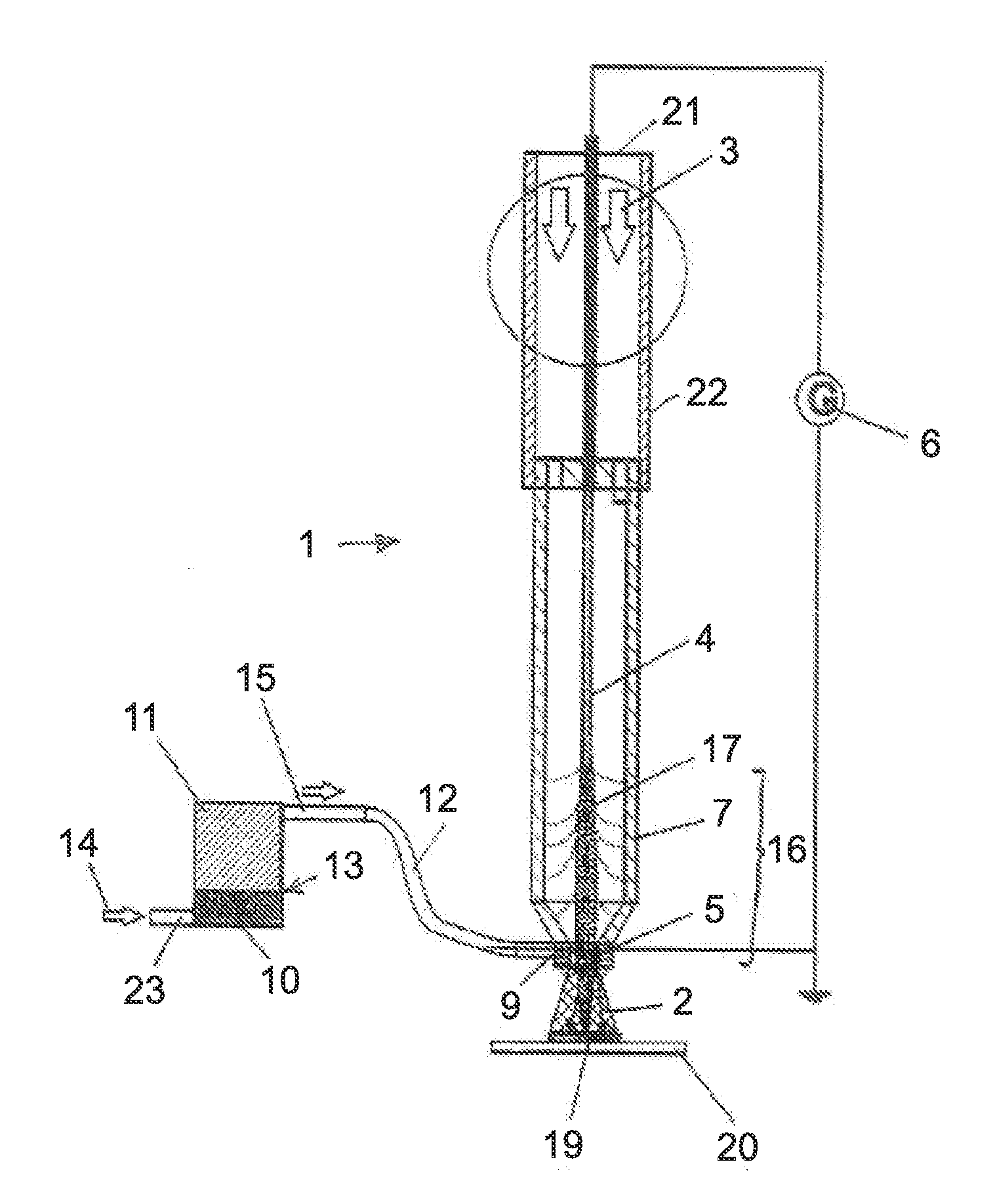
  • Coat as well as method and device for coating
  • Coat as well as method and device for coating
  • Coat as well as method and device for coating

Examples


Embodiment Construction

[0105]At the outset, it should be appreciated that like drawing numbers on different drawing views identify identical, or functionally similar, structural elements of the invention. While the present invention is described with respect to what is presently considered to be the preferred aspects, it is to be understood that the invention as claimed is not limited to the disclosed aspects.

[0106]Furthermore, it is understood that this invention is not limited to the particular methodology, materials and modifications described and, as such, may, of course, vary. It is also understood that the terminology used herein is for the purpose of describing particular aspects only, and is not intended to limit the scope of the present invention, which is limited only by the appended claims.

[0107]Unless defined otherwise, all technical and scientific terms used herein have the same meaning as commonly understood to one of ordinary skill in the art to which this invention belongs. Although any me...


PUM

PropertyMeasurementUnit
Temperatureaaaaaaaaaa
Thicknessaaaaaaaaaa
Thicknessaaaaaaaaaa

Abstract

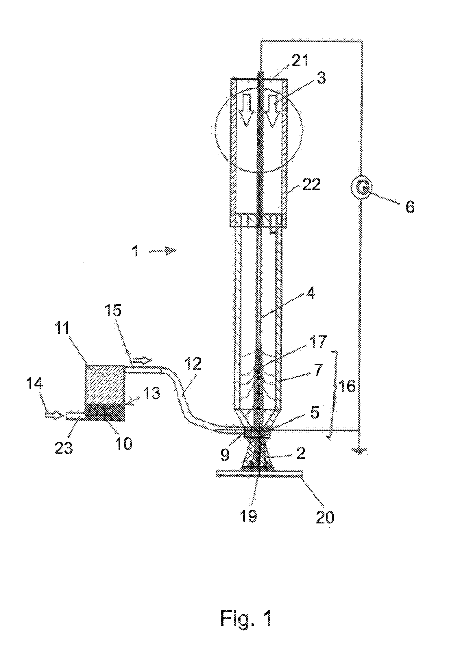
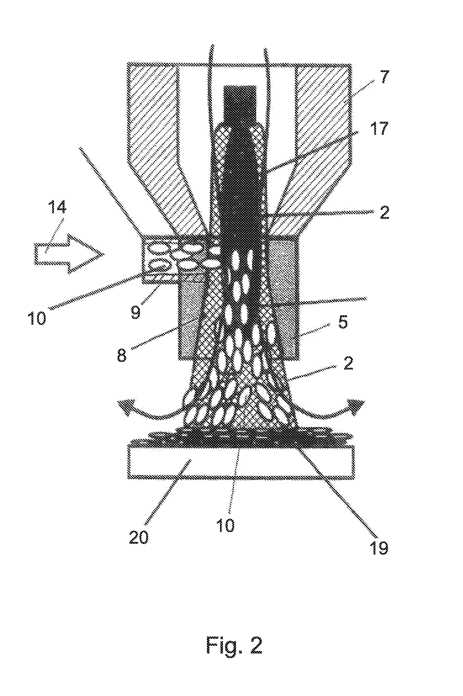
The invention relates to a method and a device for applying a coating to a substrate, where a plasma jet of a low-temperature plasma is produced by conducting a working gas through an excitation zone. The plasma jet is directed at the substrate, and plate-shaped particles having an average thickness between 10 and 50,000 nanometers and a shape factor in a value range from 10 to 2000 are fed into the plasma jet. The plate-shaped particles are fed into the plasma jet by means of a carrier gas. The plasma jet is produced by exciting the working gas by means of an alternating voltage or a pulsed direct voltage.

Description

CROSS-REFERENCE TO RELATED APPLICATIONS[0001]This application is filed under 35 U.S.C. §120 and §365(c) as a continuation of International Patent Application PCT / EP2012 / 054530, filed Mar. 15, 2012, which application claims priority from German Patent Application No. 10 2011 001 312.1, filed Mar. 16, 2011 and from German Patent Application No. 10 2011 001 982.0, filed Apr. 112, 2011, which applications are incorporated herein by reference in their entireties.FIELD OF THE INVENTION[0002]The present invention concerns a method and a device for the application of a coat onto a substrate, in which a plasma beam of a low temperature plasma is generated by leading a working gas through an excitation zone.[0003]In addition, the invention concerns a coat on a substrate made up of platelet-shaped particles that are at least partially fused with one another, as well as the use of platelet-shaped particles.BACKGROUND OF THE INVENTION[0004]The generation of layers on substrates has been known fo...

Claims


Application Information

Patent Timeline
IPC IPC(8): C23C16/50C23C16/06
CPCC23C16/50C23C16/06C23C4/12C23C8/36H05H1/34H05H1/42B05B7/1404B05B7/226C23C4/134Y10T428/257Y10T428/256B05B7/22H05H1/26
Inventor BISGES, MICHAELWOLFRUM, CHRISTIANGREB, MARCORUPPRECHT, MARKUS
Owner ECKART GMBH & CO KG
Learn More