
Supercharger Assembly

a supercharger and assembly technology, applied in the direction of pumps, mechanical equipment, electric control, etc., can solve the problems of ineffective turbochargers, single-stage turbochargers are not particularly effective at the low rate of exhaust gas flow, and ‘turbo lag’, so as to energy requirements, increase the generating capacity of the arrangement, and increase the effect of generating capacity

Active Publication Date: 2015-06-04
JAGUAR LAND ROVER LTD
View PDF9 Cites 5 Cited by
  • Summary
  • Abstract
  • Description
  • Claims
  • Application Information

AI Technical Summary

Benefits of technology

The patent describes a dual generator system that can connect a supercharger to a vehicle engine on demand, avoiding unnecessary idling. The dual generator system includes a primary generator and a secondary generator that work together to provide additional driving capacity. This allows for better performance and efficiency of the vehicle's electrical system.

Problems solved by technology

However, single-stage turbochargers are not particularly effective at the low rates of exhaust gas flow which are associated with low engine operating speeds.
This leads to the problem of ‘turbo lag’, i.e. a noticeable delay between a driver demanding power and the engine delivering the required response, because the engine speed needs to rise to a certain level before the turbocharger operates effectively.
The supercharger is driven mechanically by the engine, to perform the same task of raising the pressure, temperature and density of air in the inlet manifold when the engine is running at low speeds such that the turbocharger is ineffective.
However, as the supercharger is driven mechanically by the engine, it increases the load on the engine and thereby increases fuel consumption.
Superchargers may be driven directly from the vehicle engine, but this arrangement tends to be inflexible should the installation envelope change, for example because the engine is to be fitted to a different engine compartment.
The power requirement of the supercharger is such that it is impractical to attempt to use an electric motor in isolation to drive the supercharger in a vehicle environment.
However, this arrangement retains the disadvantage that the supercharger is permanently connected to the generator armature, and thus absorbs some energy even whilst deactivated.

Method used


Image

  • Supercharger Assembly
  • Supercharger Assembly
  • Supercharger Assembly

Examples


Embodiment Construction

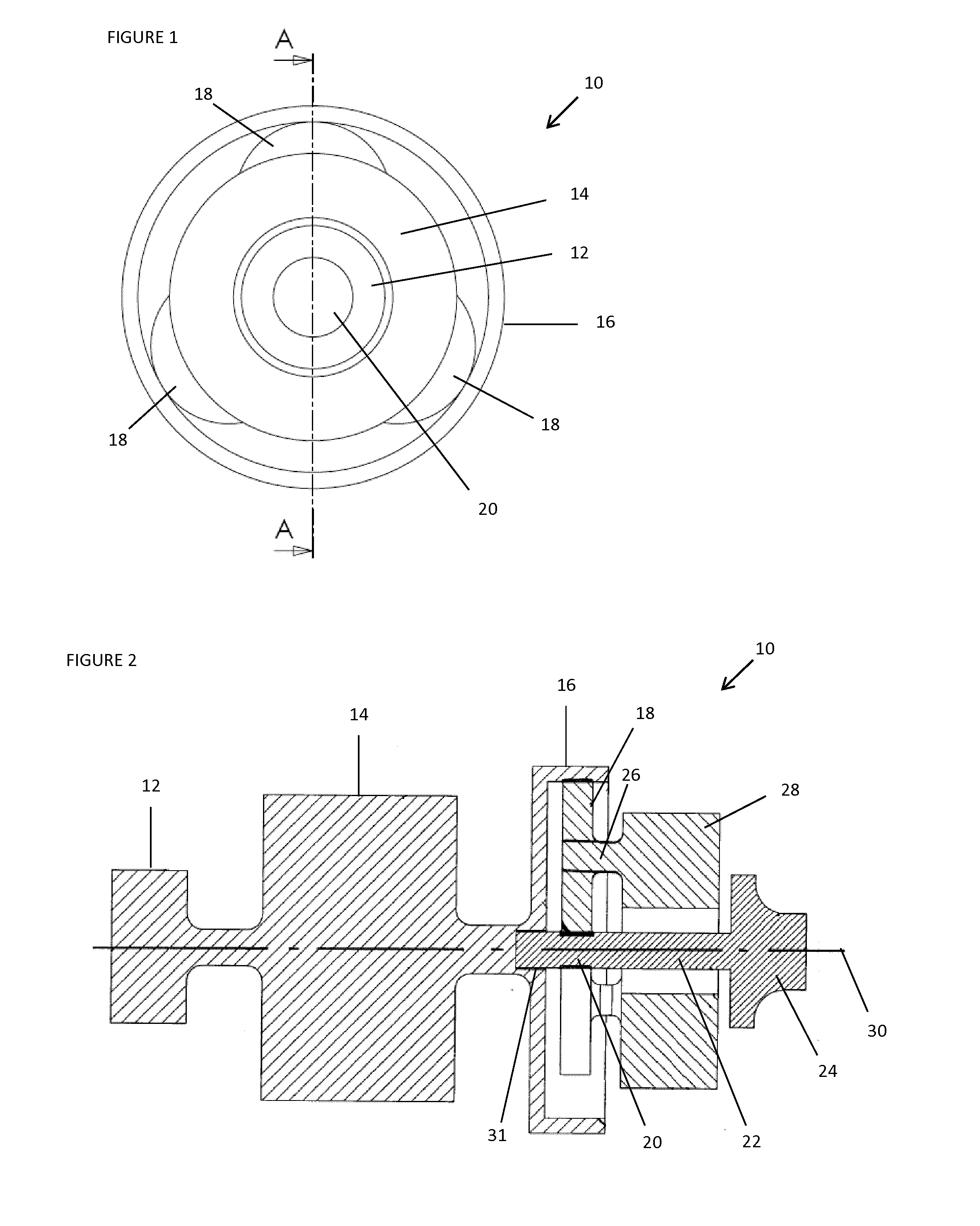
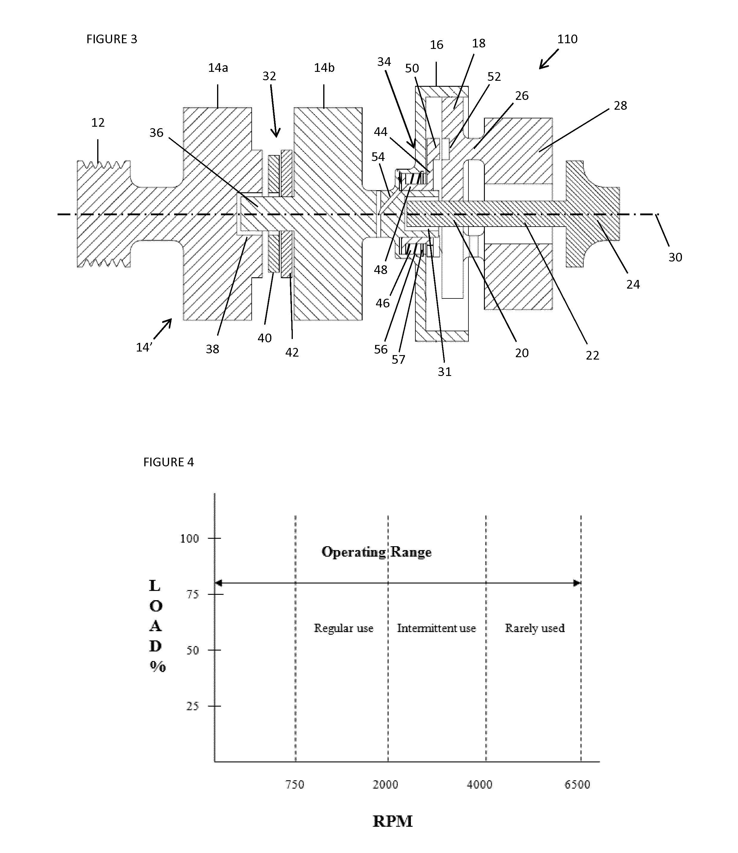
[0078]With reference to FIGS. 1 and 2, a conventional supercharger generator arrangement 10 comprises a drive pulley 12, driven by a conventional serpentine auxiliaries drive belt of a vehicle engine (not shown). The pulley 12 is coupled to an armature 14 of a vehicle generator, e.g. an alternator. The generator armature 14 is in turn coupled to an annulus 16 of an epicyclic gear train, comprising a gearing mechanism having planets 18, and a sun 20 directly connected to a drive shaft 22 of an impeller 24 of a supercharger. The planets 18 are rotatably mounted on a planet carrier 26, which is connected to an armature 28 of an electric motor, which surrounds the drive shaft 22. The planets 18 mesh with both the annulus 16 and the sun 20, such that if the planet carrier 26 is held stationary, rotation of the annulus 16 causes both the planets 18 and the sun 20 to rotate. The impeller 24 is coupled to the sun 20 via the drive shaft 22, and therefore when the sun 20 rotates, the impeller...


PUM


Abstract

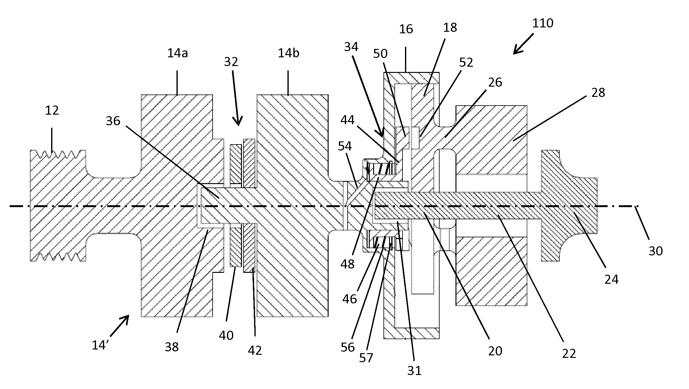
A vehicle supercharger assembly (110) comprises a dual generator comprising first and second co-axial relatively rotatable armatures (14a, 14b), and a first disengageable clutch (32) between the armatures (14a, 14), said first armature (14a) being adapted for permanent drive from a source of motive power, and said second armature (14b) being driven by said first armature (14a) on engagement of said first clutch (32); a supercharcharger impeller (24), the second armature (14b) driving the impeller (24) mechanically via a gear train; an electric motor coupled to the gear train and operable to adjust the rotational speed of the impeller (24); wherein, in use, the electric motor is electrically driven on demand from a generator comprising the second armature (14b).

Description

FIELD OF THE INVENTION[0001]This invention relates to a supercharger assembly for an internal combustion engine and in particular, but not exclusively, to electric drives comprising a generator and motor in combination and a control method for the same. Aspects of the invention relate to a generator, to a supercharger assembly, to a control unit, to a method and to a vehicle.BACKGROUND[0002]Exhaust-driven turbochargers are typically provided for internal combustion engines in order to improve their performance by increasing the pressure, temperature and density of air in an engine inlet manifold which is used to supply a fuel / air mixture to the engine cylinders. This makes it possible to burn more fuel in each cycle of the engine, thereby increasing the power output. Exhaust-driven turbochargers make use of energy contained in the engine exhaust gases which would otherwise go to waste, and therefore can contribute to an improvement in the overall efficiency of the engine. However, s...

Claims


Application Information

Patent Timeline
Patent Type & Authority Applications(United States)
IPC IPC(8): F02B39/04F02B39/10F02D41/00F02B37/04F02B39/12
CPCF02B39/04F02B37/04F02B39/10F02D41/0007F02B39/12F02B33/40F02N11/04Y02T10/12
Inventor DALE-JONES, GRAHAM
Owner JAGUAR LAND ROVER LTD
Learn More