Cooling system for server and cooling method for electronic apparatus

a cooling system and server technology, applied in the field of cooling systems, can solve the problems of inability to operate the whole server system, the cooling air blown from the conventional cooling air conditioning system to fully flow through the machine room, and the center must consume considerable power, so as to reduce the energy required, reduce the rest of the heat energy, and reduce the effect of heat energy

Active Publication Date: 2014-02-04
INVENTEC CORP
View PDF14 Cites 5 Cited by
  • Summary
  • Abstract
  • Description
  • Claims
  • Application Information

AI Technical Summary

Benefits of technology

[0013]The first cooling fluid and the second cooling fluid perform heat exchange in the heat exchanger, such that the temperature of the second cooling fluid is reduced and the energy required for the second cooling fluid to return to a set temperature is also reduced.
[0015]The cooling system comprises at least one fan module, a radiator, a first cooling loop, a second cooling loop, and a heat exchanger. The fan module is used to provide airflow being blown to the drawer, so as to reduce the temperature of the drawer, and the radiator is disposed at an air-intake vent of the fan module. The first cooling loop has a first cooling fluid which is in thermal contact with the radiator, so as to reduce the temperature of the air at the air-intake vent of the fan module, and the second cooling loop has a second cooling fluid which is in thermal contact with the first heat module. The heat exchanger provides the heat exchange for the second cooling fluid after thermal contact with the first heat module and the first cooling fluid after thermal contact with the radiator, so as to reduce the temperature of the second cooling loop and increase the temperature of the first cooling loop.
[0017]The cooling method comprises the following steps. A first cooling loop is used to reduce the temperature of an air-intake vent of a fan module, a second cooling loop is used to reduce a part of heat energy generated by the electronic apparatus, and the fan module generates airflow to dissipate the rest heat energy generated by the electronic apparatus.
[0018]The present invention has the following effects. The temperature of the second cooling fluid is reduced through the heat exchanger, so as to reduce the energy required for the second cooling fluid to return to the set temperature.
[0020]In this way, not only the whole heat dissipation performance of the cooling system of the present invention is improved, but also the power required by the cooling system of the present invention is greatly reduced, thus achieving the efficacy of energy saving and high heat dissipation performance.

Problems solved by technology

Therefore, the large-quantity and closely-arranged servers and other devices cause too much heat, thus causing the unstable operation of the whole server system, which is an important problem necessarily faced by a data center all the time.
However, because of the increased number of the servers and the closer arrangement of the cabinets, the cooling air blown from the conventional cooling air conditioning system fails to fully flow everywhere of the machine room, such that the heat air tends to centralize in certain areas to the unsteadiness of the server system.
Therefore, the data center must consume considerable power to cool the cooling water, thus causing poor power usage effectiveness (PUE).
Moreover, since the cooling water of the conventional ice water circulating type cooling device directly cool the server system through pipeline transmission, the operation temperature of the cooling water cannot be controlled, so that it is impossible to precisely control the operation temperature of a plurality of server systems of the data center.
At the same time, since the server system is lack of the installation of firmware, it is impossible to control the internal pressure of the cooling device.

Method used


Image

  • Cooling system for server and cooling method for electronic apparatus
  • Cooling system for server and cooling method for electronic apparatus
  • Cooling system for server and cooling method for electronic apparatus

Examples


first embodiment

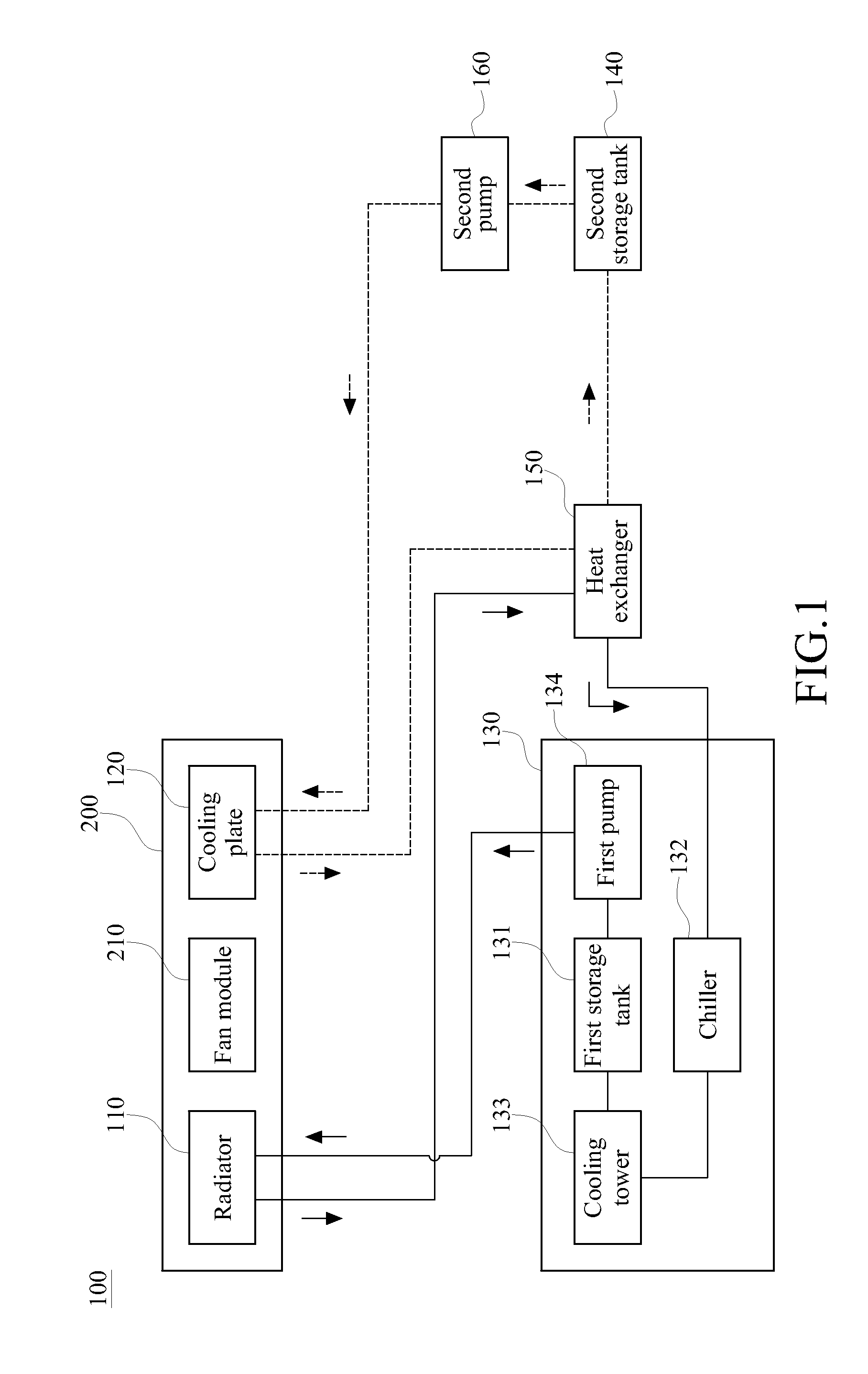
[0028]FIG. 1 is a schematic view of a system according to the present invention, and FIG. 5 is a flow chart of steps of a cooling method for an electronic apparatus according to the present invention. As shown in the drawings, a cooling system 100 of the present invention is applicable for heat dissipation and temperature reducing of a server cabinet 200, in which at least one fan module 210 is disposed in the server cabinet 200, so as to perform heat dissipation on the electronic components of the server through convection. A thermograph (not shown) may be disposed in the server cabinet 200 to monitor the internal temperature thereof.

[0029]The server cabinet 200 shown in FIG. 4 comprises a rack 200, a drawer 230, at least one circuit board 240, and at least one fan module 210. The drawer 230 and the circuit board 240 are mounted in the rack 220, and the fan module 210 is also mounted on the rack 220 and generates airflow being blown to the circuit board 240 for heat dissipation. Ho...

second embodiment

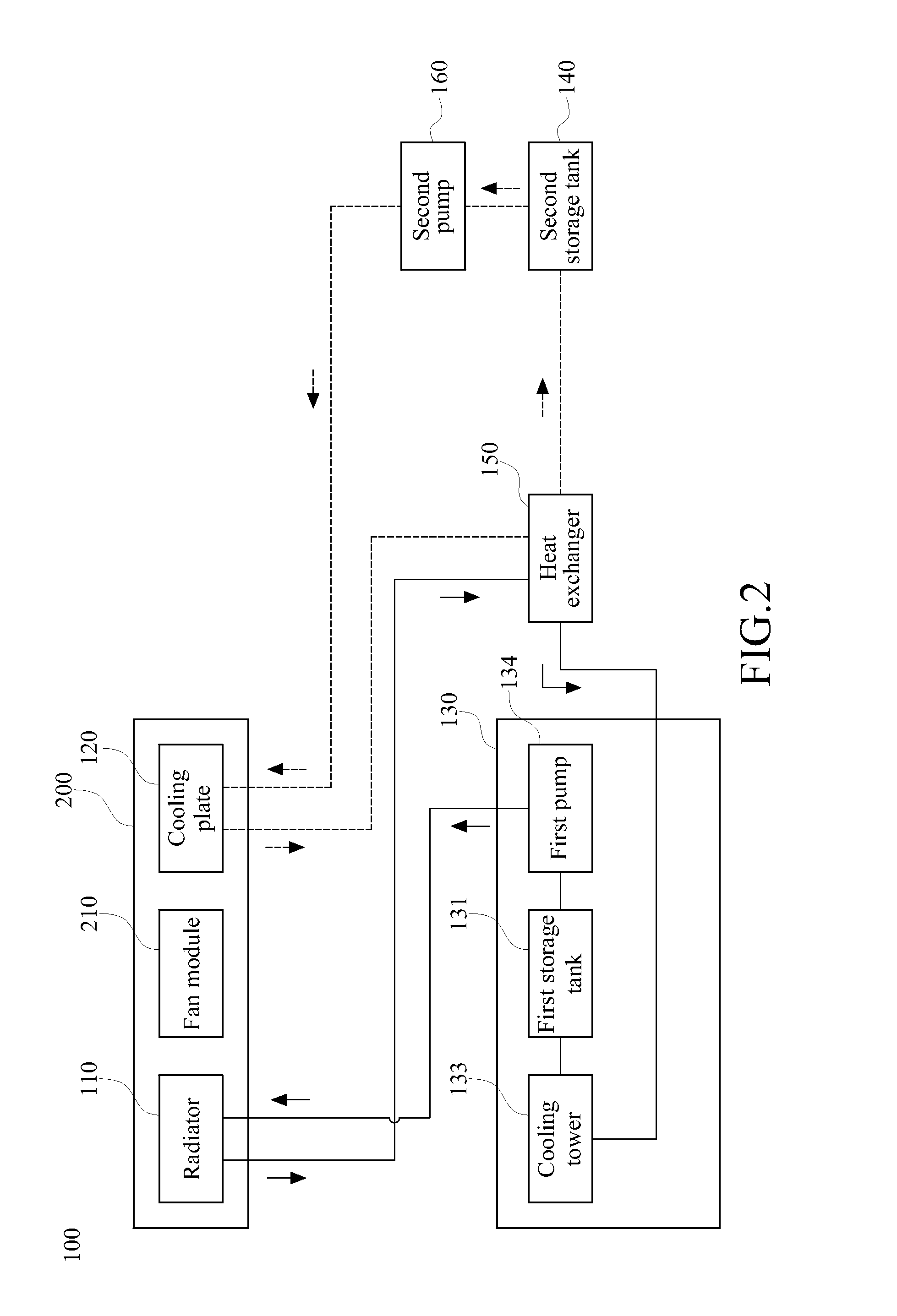
[0044]As shown in FIG. 2, a cooling system 100 of the second embodiment comprises a radiator 110, a cooling plate 120, a cooling assembly 130, a second storage tank 140, and a heat exchanger 150. The cooling assembly 130 comprises a first storage tank 131, a cooling tower 133, and a first pump 134, and further comprises a chiller 132 connected to the heat exchanger 150 and the cooling tower 133.

[0045]When the first cooling fluid after heating up flows back to the cooling assembly 130 to be cooled, the chiller 132 first provides the process of cooling, and the first cooling fluid is sprayed in atomization in the cooling tower 133 to perform secondary cooling.

[0046]The chiller 132 provided by this embodiment is in the auxiliary use to increase the heat dissipation velocity of the first cooling fluid, or the chiller 132 is used as a backup during the cooling of the first cooling fluid, which operates in the case that the temperature difference between the first cooling fluid and the en...

third embodiment

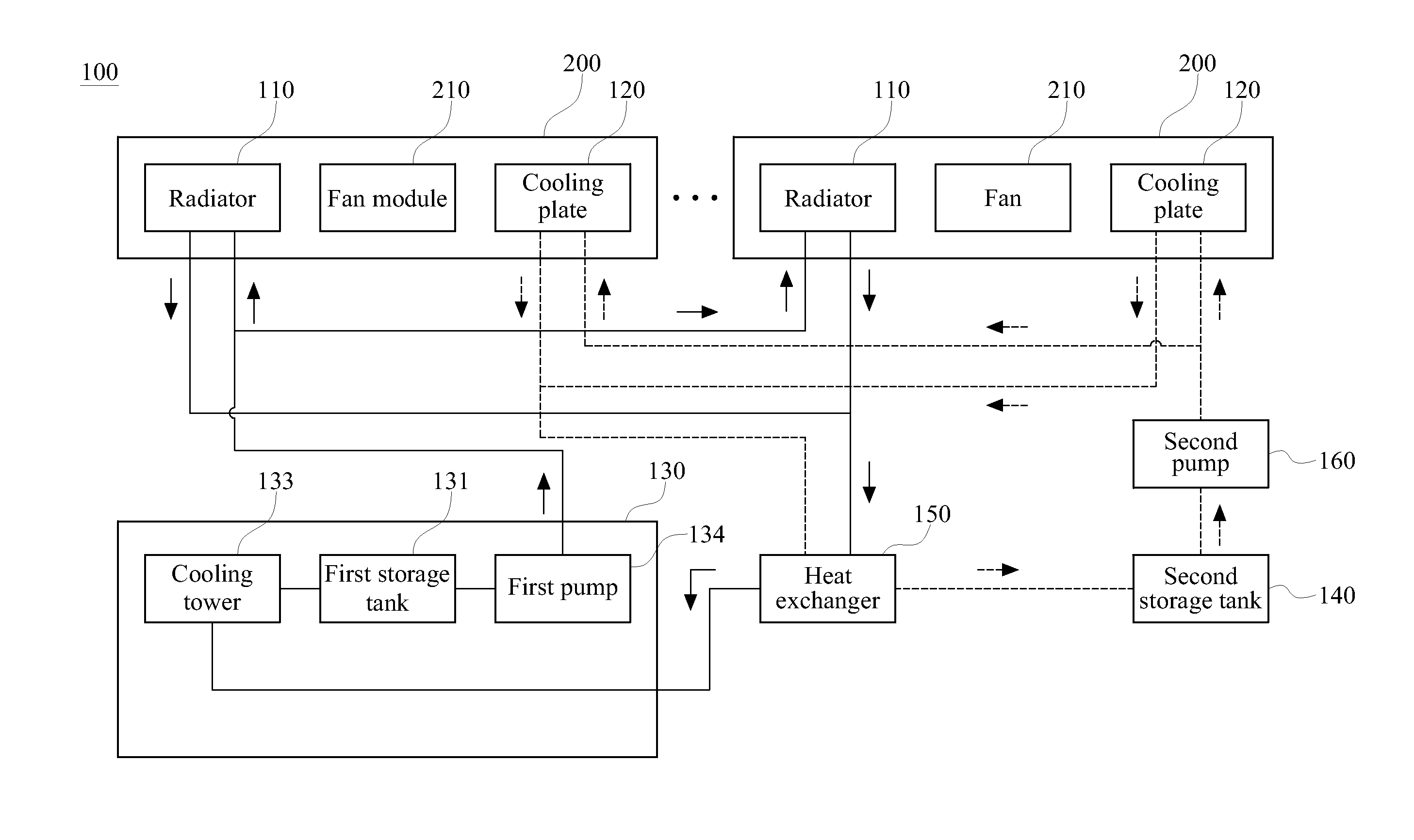
[0048]A cooling system 100 in the third embodiment is applicable for heat dissipation and cooling of a plurality of server cabinets 200, for example, the heat dissipation is performed on a data center formed by a large number of server cabinets in series connection.

[0049]The cooling system 100 of the third embodiment of the present invention comprises a plurality of radiators 110, a plurality of cooling plates 120, a cooling assembly 130, a second storage tank 140, and a heat exchanger 150. The radiators 110 and the cooling plates 120 are respectively disposed in the server cabinets 200.

[0050]The cooling assembly 130 in this embodiment comprises a first storage tank 131, a cooling tower 133, and a first pump 134. A first cooling fluid, such as water, a coolant or a high-temperature coolant, is carried in the first storage tank 131, which is not limited to this embodiment. The cooling tower 133 is connected to the heat exchanger 150 and the first storage tank 131, and the first pump ...


PUM


Abstract

A cooling system for a server includes at least one radiator and at least one cooling plate that are installed in a server cabinet, a cooling assembly, a storage tank, and a heat exchanger. The cooling assembly is connected to the radiator, and is carried with a first cooling fluid therein. The storage tank is connected to the cooling plate, and is carried with a second cooling fluid therein. The first cooling fluid enters the heat exchanger through the radiator, and the second cooling fluid enters the heat exchanger through the cooling plate. The first cooling fluid and the second cooling fluid perform heat exchange in the heat exchanger, so as to reduce the temperature of the second cooling fluid, thus reducing the required energy enabling the second cooling fluid to return to a set temperature.

Description

CROSS-REFERENCE TO RELATED APPLICATIONS[0001]This non-provisional application claims priority under 35 U.S.C. §119(a) on Patent Application No(s). 099138213 filed in Taiwan, R.O.C. on Nov. 5, 2010, the entire contents of which are hereby incorporated by reference.BACKGROUND OF THE INVENTION[0002]1. Field of Invention[0003]The present invention relates to a cooling system, in particular, to a cooling system and a cooling method applicable to a server cabinet.[0004]2. Related Art[0005]In recent years, with the fast and vigorous development of the Internet, particularly in some large enterprises or cyber cafes, due to the service increasing requirement, the number of the servers increases, so that the arrangement of the servers becomes more centralized to save the space occupied by the servers. Therefore, the large-quantity and closely-arranged servers and other devices cause too much heat, thus causing the unstable operation of the whole server system, which is an important problem ne...

Claims


Application Information

Patent Timeline
Patent Type & Authority Patents(United States)
IPC IPC(8): H05K7/20
CPCH05K7/20781
Inventor CHEN, CHIEN-AN
Owner INVENTEC CORP
Why Eureka
Try Eureka