
B column on vehicle and manufacturing method

A manufacturing method and B-pillar technology, applied to vehicle components, upper structure, upper structure sub-assembly, etc., can solve the problems of impact force endangering driver safety, not conforming to the lightweight trend, and heavy weight of cold stamping parts, etc., to achieve Light weight, easy part springback, uniform load effect

Inactive Publication Date: 2015-04-29
WUXI LANGXIAN LIGHTWEIGHT TECH CO LTD
View PDF6 Cites 2 Cited by
  • Summary
  • Abstract
  • Description
  • Claims
  • Application Information

AI Technical Summary

Problems solved by technology

The advantage of adopting the structure of B-pillar with variable thickness is that it can better protect the driver and passengers, and can achieve the purpose of deformation and energy absorption in the event of a collision; while the traditional method of welding steel plates with the same thickness has the following defects: (1) B-pillar and reinforced steel plates are generally cold stamped parts, which require new molds and welding tools; (2) cold stamped parts of the same strength are heavy and do not conform to the trend of lightweight; (3) B-pillars and reinforced steel plates are formed separately Matching welding is realized, the stability is not high, the quality control is difficult, and the scrap rate is high; (4) The strength of the upper and lower B-pillars is the same. When a side collision occurs, there is no energy-absorbing deformation part, and the huge impact force will endanger the safety of the driver.

Method used


Image

  • B column on vehicle and manufacturing method
  • B column on vehicle and manufacturing method

Examples


Embodiment Construction

[0018] The present invention will be further described below in conjunction with specific drawings.

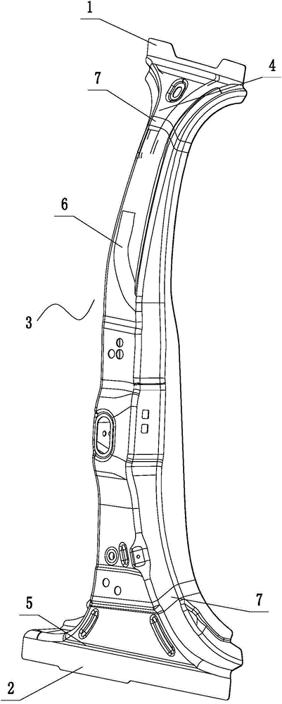
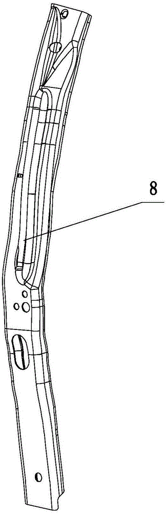
[0019] Such as Figure 1 ~ Figure 2 As shown: the B-pillar on the vehicle includes an upper fixing part 1, a lower fixing part 2, a B-pillar main body 3, a first thickness area 4, a second thickness area 5, a third thickness area 6, a transition area 7, and a reinforcing tube 8 etc.

[0020] Such as figure 1 , figure 2 As shown, the present invention includes a B-pillar main body 3, the top of the B-pillar main body 3 is an upper fixing part 1 fixed to the roof, and the bottom of the B-pillar main body 3 is a lower fixing part 2 fixed to the door sill; the upper part of the B-pillar main body 3 It is the first thickness region 4, the lower part is the second thickness region 5, the middle part is the third thickness region 6, and the transition region 7 is between the first thickness region 4, the second thickness region 5 and the third thickness region 6; The thickness o...


PUM


Abstract

The invention relates to a B column on a vehicle and a manufacturing method. The B column comprises a B column main body, wherein the top of the B column main body is provided with an upper fixing part fixed together with a vehicle roof; the bottom of the B column main body is provided with a lower fixing part fixed together with a threshold. The B column is characterized in that the upper part of the B column main body is a first thickness region; the lower part of the B column main body is a second thickness region; the middle of the B column main body is a third thickness region; transition regions are formed among the first thickness region, the second thickness region and the third thickness region; the thicknesses of the first thickness region and the second thickness region are 1.2 millimeters; the thickness of the third thickness region is 2 millimeters; in the transition regions, the thickness of the third thickness region gradually decreases to the thicknesses of the first thickness region and the second thickness region; a reinforcing pipe is arranged in the third thickness region; the reinforcing pipe is a hollow pipe, and is made through a hydraulic forming process. By adopting the hydraulically-formed reinforcing pipe, the section design of the reinforcing pipe can be flexibly changed according to the shape of the B column, so that each section is loaded more uniformly.

Description

technical field [0001] The invention relates to a B-pillar on a vehicle and a manufacturing method, belonging to the technical field of vehicle components. Background technique [0002] A car's B-pillar is the vertical beam on the car that sits between the front and rear seats of the cockpit and extends from the roof to the bottom of the car. The B-pillar not only supports the roof cover, but also bears the supporting force of the front and rear doors. Some additional parts are also installed on the B-pillar, such as the seat belts of the front seats, and sometimes the wiring harness. Therefore, most of the B-pillars have a convex radius to ensure better force transmission performance. The cross-sectional shape of the B-pillar of a modern car is relatively complicated, and it is welded by multiple pieces of stamped steel plates. With the development of automobile manufacturing technology, a closed cross-section center column that directly adopts hydroforming without weldin...

Claims


Application Information

Patent Timeline
IPC IPC(8): B62D25/04B23P15/00
CPCB62D25/04B23P15/00
Inventor 孙财陈扬李向荣杨云龙
Owner WUXI LANGXIAN LIGHTWEIGHT TECH CO LTD
Features
  • Generate Ideas
  • Intellectual Property
  • Life Sciences
  • Materials
  • Tech Scout
  • Unparalleled Data Quality
  • Higher Quality Content
  • 60% Fewer Hallucinations
Learn More