Cam-driven hydraulic fully variably valve mechanism of internal combustion engine

A technology of valve mechanism and internal combustion engine, which is applied in the direction of internal combustion piston engine, valve driving device, engine components, etc. It can solve the problems of large volume, inability to flexibly control valve lift and valve timing, complex structure, etc., and achieve large fluid flow inertia , improve fuel economy, improve the effect of cold start

Inactive Publication Date: 2015-04-29
JILIN UNIV
View PDF5 Cites 29 Cited by
  • Summary
  • Abstract
  • Description
  • Claims
  • Application Information

AI Technical Summary

Problems solved by technology

[0004] The purpose of the present invention is to overcome the shortcomings of the existing variable valve mechanism, such as complex structure, large volume, and inability to flexibly control the valve

Method used


Image

  • Cam-driven hydraulic fully variably valve mechanism of internal combustion engine
  • Cam-driven hydraulic fully variably valve mechanism of internal combustion engine
  • Cam-driven hydraulic fully variably valve mechanism of internal combustion engine

Examples


Embodiment Construction

[0024] The present invention is described in detail below in conjunction with accompanying drawing:

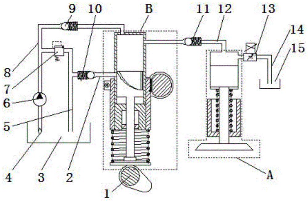
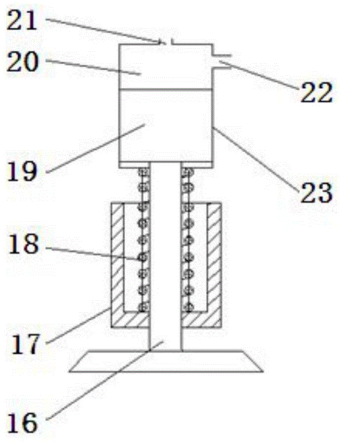
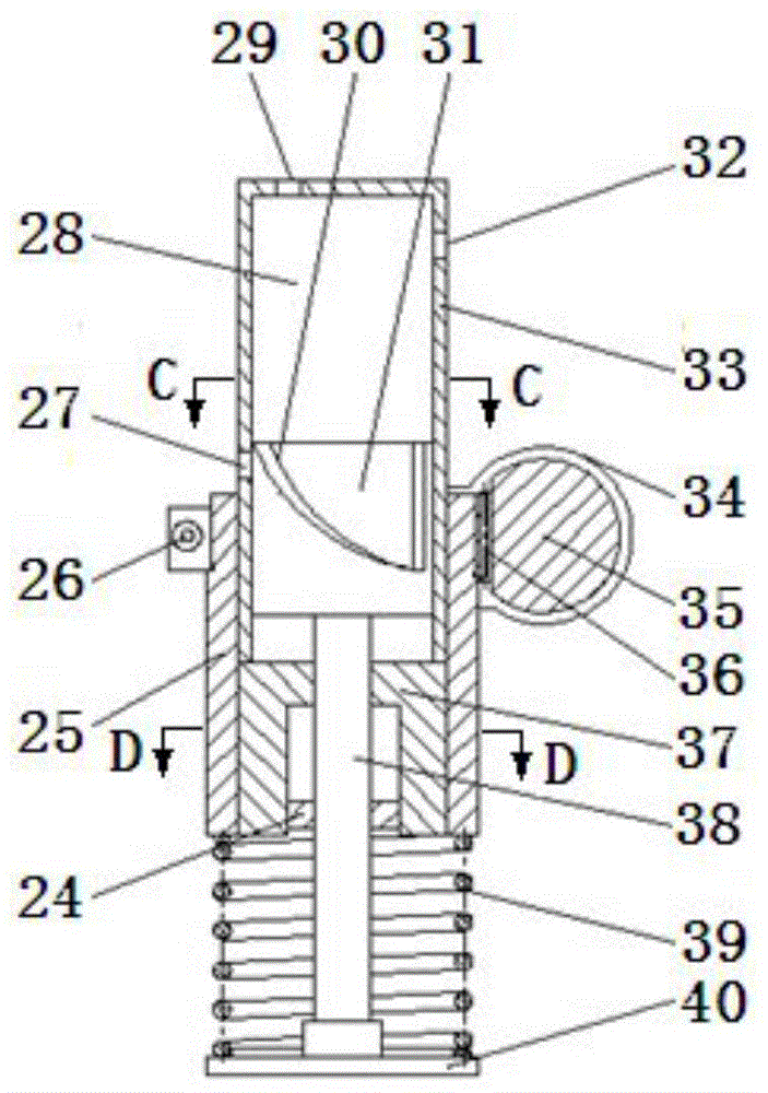
[0025] The present invention consists of hydraulic piston valve group A, tappet group B, cam 1, oil pipe I2, oil tank I3, filter 4, oil pipe II5, oil pump 6, overflow valve 7, oil pipe III8, one-way valve I9, one-way Valve II10, one-way valve III11, oil pipe IV12, electro-hydraulic proportional valve 13, oil pipe V14 and oil tank II15, the hydraulic piston valve group A is composed of valve 16, valve spring seat I17, valve spring I18, valve piston 19, piston Cavity 20 and piston sleeve 23 are formed, and described tappet group B is made up of tongue 24, oil amount adjustment sleeve 25, ring gear clamping screw 26, tappet cavity 28, spiral groove 30, tappet piston 31, tappet Cover 33, oil quantity adjustment tooth bar sleeve 34, oil quantity adjustment tooth bar 35, ring gear 36, tongue groove 37, piston rod 38, spring II 39, spring seat II 40 form.

[0026] Refer to attached ...


PUM


Abstract

A cam-driven hydraulic fully variable valve mechanism of an internal combustion engine belongs to the technical field of engines. An inlet end of an oil tube III is arranged in an oil tank I, an outlet end of the oil tube is fixedly connected with an oil inlet hole I. The inlet end of the oil tube III is provided with a filter. An oil pump, an inlet end of an oil tube II and a check valve I are connected with the oil tube III in series. An overflow valve and an outlet end of an oil tube I are connected with the oil tube II in series. An outlet end of the oil tube II is arranged in the oil tank I. An inlet end of the oil tube I is fixedly connected with an oil drainage hole. The middle of the oil tube I is provided with a check valve II. The inlet end of an oil tube V is fixedly connected with an oil drainage hole II. The outlet end of the oil tube V is arranged in the oil tank II. An electro-hydraulic proportional valve is arranged adjacent to the inlet end of the oil tube V. The two ends of an oil tube IV are respectively communicated with a connecting hole and an oil inlet hole II of a tappet group. A check valve II is arranged in the middle of the oil tube IV. The cam-driven hydraulic fully variable valve mechanism of the internal combustion engine can realize continuous variable of valve lift and valve timing and throttle-free load control of a gasoline engine, reduce pumping loss, improve the volumetric efficiency, realize the Miller cycle, achieves the effect of energy saving and emission reduction, and is simple in structure and flexible in control.

Description

technical field [0001] The invention belongs to the technical field of engines, and in particular relates to a hydraulic fully variable valve mechanism of a cam-driven internal combustion engine. Background technique [0002] Due to the fixed structure of the traditional engine's valve mechanism, the valve timing cannot be changed during the operation of the engine. Usually, it can only ensure the performance of the internal combustion engine in a certain working condition, and it cannot take into account the requirements of various working conditions at the same time. It is difficult To achieve the real optimal valve timing. These fixed valve operating parameters are just a compromise of various comprehensive contradictions of internal combustion engine operation requirements for valve work under different operating conditions. Therefore, in order to meet the different valve timing requirements under different working conditions, improve the economy and power of the intern...

Claims


Application Information

Patent Timeline
IPC IPC(8): F01L1/34F01L13/00F01L9/02F01L1/04F01L9/11
CPCF01L1/04F01L1/34F01L13/00F01L9/10Y02T10/12
Inventor 钟兵洪伟解方喜苏岩张富伟李翔宇韩林沛姜伟陈静王鑫峰
Owner JILIN UNIV
Why Eureka
Try Eureka