Box liquid level sensor

A liquid level sensor and tank technology, applied in liquid level indicators, instruments, machines/engines, etc., can solve the problems of easy crystallization and blockage of urea solution, complex structure of liquid level sensor, high sealing requirements, etc., to achieve product resistance Good vibration performance, solve the problem of exhaust emission, and strong ability to adapt to the environment

Inactive Publication Date: 2015-04-29
FIRSTRATE SENSOR
View PDF4 Cites 4 Cited by
  • Summary
  • Abstract
  • Description
  • Claims
  • Application Information

AI Technical Summary

Problems solved by technology

However, the structure of the existing liquid level sensor used in the urea tank is relatively complicated, which is basically the same as the structure of the liquid level sensor used in the oil tank
At present, the structure of the liquid level sensor used in the urea tank includes a fixing seat, a water pipe and an electronic tube, etc., and most of the fixing seats are plastic head fixing seats, and there is no air pipe joint on the plastic head fixing seat; the plastic head fixing seat and the The heating water pipe is fixedly connected, but long-term use often causes it to shake, which affects the performance and has poor anti-vibration performance; the heating water pipe is divided into two sections: the pipe body and the joint, and the two sections are fixed and connected with plastic heads, which is troublesome to assemble. The manufacturing cost is high, and the leakage problem is difficult to control; in addition, the heating water pipe is relatively small, with a diameter of 10mm, fixed by a single heat conducting plate, and the heat conduction speed is slow, and the urea solution is easy to crystallize and block the urea suction pipe and urea connector; the plastic head fixing seat is One-piece molding, high sealing requirements, difficult process control, difficult to carry out after-sales maintenance

Method used


Image

  • Box liquid level sensor
  • Box liquid level sensor

Examples


Embodiment Construction

[0020] The present invention will be further described below in conjunction with drawings and embodiments.

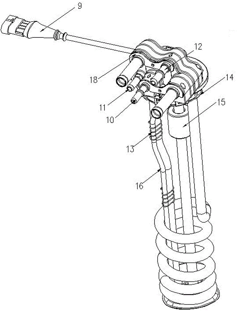
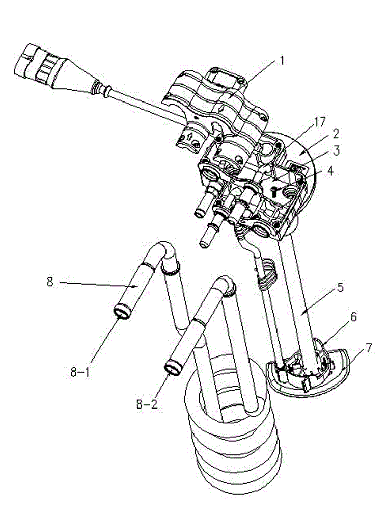
[0021] refer to figure 1 , figure 2 , a tank liquid level sensor, including a fixed seat, one side of the fixed seat is provided with a connector 9 for transmitting signals, the fixed seat is composed of a fixed seat main body 2 and an upper cover 1, and there is an electronic tube 5 under the fixed seat main body 2 , the upper end of the electronic tube 5 is installed on the main body 2 of the fixed seat, the magnetic buoy 15 that can move up and down along the electronic tube 5 is installed on the electronic tube 5, and the urea suction tube 16 that can extend into the inside of the urea tank is equipped with the bottom of the fixed seat main body 2. Pipe 17 and hot water pipe 8; the head end of the urea suction pipe 16 is provided with a urea suction pipe joint 10, the head end of the urea return pipe is provided with a urea return pipe joint 12, and the hot water ...


PUM


Abstract

Disclosed is a box liquid level sensor. The box liquid level sensor comprises a fixing seat, wherein the fixing seat is composed of a fixing seat main body and an upper cover, an electronic pipe is arranged below the fixing seat main body, the upper end of the electronic pipe is installed on the fixing seat main body, a magnetic float cylinder is installed on the electronic pipe, a urea suction pipe, a urea return pipe and a hot water pipe, which can be stretched into a urea box, are assembled below the fixing seat main body, a water inlet and a water outlet are formed in the hot water pipe, a urea suction pipe connector, a urea return pipe connector, and the water inlet and the water outlet of the hot water pipe are all installed on the fixing seat main body, a first heat conducting fin is arranged in the fixing seat, the first heat conducting fin is placed between the fixing seat main body and the upper cover, and a second heat conducting fin is installed in front of the fixing seat main body. The box liquid level sensor is compact in structure, stable in performance, good in vibration resisting performance, good in sealing performance, easy to assemble, low in manufacture cost, strong in environmental adaptability, and suitable for cold regional environments.

Description

technical field [0001] The invention relates to a tank liquid level sensor, in particular to a sensor which is placed in the tank to measure the liquid level and has a heating function. Background technique [0002] Diesel engines have been widely used in various industries around the world due to their high thermal efficiency and low exhaust emissions, but their high nitrogen oxide emissions have always been a problem that plagues people. Since the 1990s, with the continuous stringent emission regulations of fuel (gas) vehicle engines around the world, the continuous development of engine technology has been promoted. On July 1, 2008, my country began to implement the National III emission regulations, and on January 1, 2010, the National IV emission regulations were implemented. In the fierce market competition, manufacturers have to improve or develop engines according to emission standards. At present, the technical routes to achieve the National IV emission standard i...

Claims


Application Information

Patent Timeline
Patent Type & Authority Applications(China)
IPC IPC(8): F01N3/24G01F23/00
Inventor 杨明伟董安陈超旺倪思虎
Owner FIRSTRATE SENSOR
Why Eureka
Try Eureka