Compressed air energy storage system

A compressed air energy storage and energy storage technology, which is applied in the direction of gas turbine devices, machines/engines, mechanical equipment, etc., can solve the problem of demanding gas storage conditions in compressed air energy storage power stations, difficulties in natural gas supply, and impacts on compressed air energy storage technology Problems such as popularization and application, to achieve the effect of reducing the requirements of site selection conditions and increasing the overall output

Active Publication Date: 2015-04-29
CHINA ENERGY ENG GRP GUANGDONG ELECTRIC POWER DESIGN INST CO LTD
View PDF10 Cites 17 Cited by
  • Summary
  • Abstract
  • Description
  • Claims
  • Application Information

AI Technical Summary

Problems solved by technology

[0003] Most of the existing compressed air energy storage systems separate the energy storage stage from the energy release stage, and increase the electric energy capacity of the compressed air energy storage system by increasing the volume of the gas storage chamber and increasing the storage pressure of the compressed air. The compressed air energy storage power station has very strict requirements on the gas storage conditions
On the other hand, if the combustor is arranged in the compressed air energy storage system, it may affect the popularization and application of compressed air energy storage technology due to the difficulty of natural gas supply in remote areas

Method used


Image

  • Compressed air energy storage system
  • Compressed air energy storage system
  • Compressed air energy storage system

Examples


Embodiment Construction

[0029] Embodiments of the present invention are described in detail below:

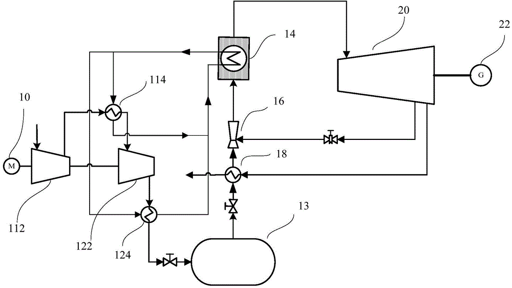
[0030] Such as figure 1 As shown, a compressed air energy storage system includes an energy storage part and an energy release part, and the energy release part includes an ejector 16, a first heat storage / heat exchanger 14, a turbo expander 20 and a generator 22 , the energy storage part is connected to the inlet of the ejector 16, and the outlet of the ejector 16 is connected to the first heat storage / heat exchanger 14, and the first heat storage / heat exchanger 14 is connected to the The inlet of the turboexpander 20 is connected, the entrainment port of the ejector 16 is connected to the turboexpander 20 for air extraction, and the turboexpander 20 is connected to the generator 22 .

[0031] In the energy release part of the compressed air energy storage system, the air compressor in the energy storage part injects compressed air into the air storage chamber 13, and at the same time, the compresse...


PUM


Abstract

The invention discloses a compressed air energy storage system comprising an energy storage part and an energy release part, wherein the energy release part comprises an ejector, a first heat storage/exchange device, a turbo-expander and a generator; the energy storage part is connected with an inlet of the ejector; an outlet of the ejector is connected with the first heat storage/exchange device; the first heat storage/exchange device is connected with an inlet of the turbo-expander; an entraining hole of the ejector is connected with the turbo-expander to realize air exhaust; and the turbo-expander is connected with the generator. An air compressor of the energy storage part of the compressed air energy storage system is used for injecting compressed air into an air storage chamber, the compressed air flows out from an outlet of the gas storage chamber and enters the ejector, low-pressure exhausted air of the turbo-expander enters from the entraining hole of the ejector, the mixing of high-pressure air and low-pressure air is realized in the ejector, then the mixed air is heated in the first heat storage/exchange device, and the heated airflow enters the turbo-expander to do work and drive the generator to output stable electric energy.

Description

technical field [0001] The invention relates to the technical field of energy storage, in particular to a compressed air energy storage system. Background technique [0002] The heat storage / heat exchanger can store temporarily unused heat, and exchange the stored heat through the built-in heat exchanger when needed. The compressed air energy storage system has the function of improving the quality of new energy such as wind power and solar power generation. In the energy storage stage, the electric energy with poor quality can be used to drive the air compressor to do work to obtain high-pressure air; in the energy release stage, release the compressed air. The air is used to drive the turbo expander to do work, which again drives the electric motor to output electric energy. Through compressed air energy storage technology, low-grade new energy electric energy can be converted into high-quality electric energy with stable output. [0003] Most of the existing compressed ...

Claims


Application Information

Patent Timeline
Patent Type & Authority Applications(China)
IPC IPC(8): F02C6/16F01D15/10
CPCY02E60/16
Inventor 邓广义郭祚刚范永春李伟科邓成刚
Owner CHINA ENERGY ENG GRP GUANGDONG ELECTRIC POWER DESIGN INST CO LTD
Why Eureka
Try Eureka