Air returning type fan filter unit (FFU) below ceiling

A fan filter unit, air-type technology, applied in pump components, mechanical equipment, non-variable-capacity pumps, etc., can solve the problems of increased aerodynamic noise, large flow channel resistance, and the flow channel is not optimized, so as to prolong the replacement cycle. , Reasonable airflow organization and the effect of increasing dust holding capacity

Active Publication Date: 2015-04-29
TIANJIN UNIV
View PDF12 Cites 8 Cited by
  • Summary
  • Abstract
  • Description
  • Claims
  • Application Information

AI Technical Summary

Problems solved by technology

However, at present, the technology of domestic FFU production plants is uneven, and the lack of unified standards has affected the industrialization process, especially the following problems: the noise has not been reduced for a long time, generally reaching 52dB; the design of filter material replacement and fan maintenance Unreasonable, which increases the difficulty of maintenance; the flow channel is not optimized, and the rated air supply volume cannot be well satisfied
Disadvantages of this design: 1) The upper return air needs to ensure that the room is a non-sealed ceiling, otherwise the return air pipeline needs to be installed, which makes the construction complicated and increases the investment; 2) The noise reduction design only considers the flow channel for aerodynamic noise The optimized design failed to fundamentally eliminate the noise generated by the vibration of the fan, and this part of the noise accounted for a greater proportion; 3) The filter material is

Method used


Image

  • Air returning type fan filter unit (FFU) below ceiling
  • Air returning type fan filter unit (FFU) below ceiling

Examples


Embodiment Construction

[0017] The technical solutions of the present invention will be clearly and completely described below in conjunction with the accompanying drawings in the embodiments of the present invention.

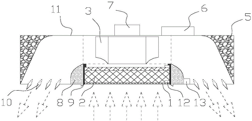
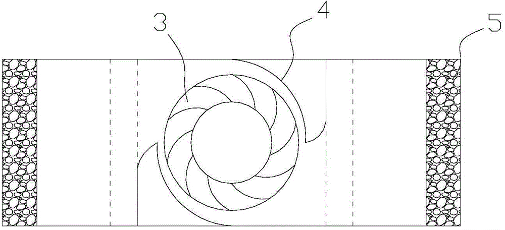
[0018] As shown in the accompanying drawings, a return air fan filter unit under the suspended ceiling of the present invention includes a box body 11 and a controller 6, and a return air port is opened in the middle of the bottom surface of the box body, and on both sides of the return air port Air outlets 10 are respectively arranged on the bottom surface of the box body, and a filter material unit is installed through a connection structure at the air return port. As a preferred embodiment of the present invention, the filter material unit is composed of return air outlet net 1, The multi-layer composite filter material 2 arranged on the return air outlet net 1 and the filter material support 9 sleeved on the outside of the return air outlet net 1 and the multi-layer composite filte...


PUM

PropertyMeasurementUnit
Diameteraaaaaaaaaa

Abstract

The invention discloses an air returning type fan filter unit (FFU) below a ceiling. The air returning type FFU below the ceiling comprises a box body and a controller; an air returning opening is formed in the middle of the bottom surface of the box body; air outlets are respectively formed in the box body bottom surfaces at two sides of the air returning opening; material filtering units are mounted at the air returning openings through connecting structures; a centrifugal fan is mounted in the box body above each material filtering unit and is connected with a motor, wherein the motor is connected with the controller; a pair of volutes which is oppositely mounted on any group of diagonal angles of a rectangular area surrounding the centrifugal fan; the projection of the sidewalls of the volutes, opposite to the centrifugal fan on the level is in a form of a spiral of Archimedes. With the adoption of the air returning type FFU below the ceiling, the air returning structure is adopted, so that the applicable scope of FFU is expanded to some extent, and the limitation from the ceiling is avoided; the air flowing structure in the FFU is reasonable; the flowing resistance of liquid in the device is reduced, and thus the energy consumption is decreased.

Description

technical field [0001] The invention relates to an air filter structure, in particular to an air return type fan filter unit under a suspended ceiling. Background technique [0002] Fan filter unit is also known as FFU (Fan Filter Units). The air supply port, self-cleaner, and laminar flow hood of the high-efficiency filter with fan commonly used in clean engineering are the prototypes of FFU. In the past two decades or so, FFU has gradually appeared in clean rooms and other places as an independent terminal equipment. The emergence of FFU makes the system structure simple, flexible, energy-saving operation, automatic control, reliable sealing, can reduce the height of the building, shorten the construction period, especially suitable for high-clean systems and local clean environments. However, at present, the technology of domestic FFU production plants is uneven, and the lack of uniform standards has affected the industrialization process, especially the following proble...

Claims


Application Information

Patent Timeline
IPC IPC(8): F04D25/08F04D29/42F04D29/44F04D29/66F04D29/70F04D27/00
CPCF04D25/088F04D27/00F04D29/4233F04D29/441F04D29/663F04D29/703
Inventor 刘俊杰李佳钰侯跃飞王志强
Owner TIANJIN UNIV
Why Eureka
Try Eureka