
Dispersed light source radiating type LED assembled lamp

A technology of LED combination lamp and LED light bulb, which is applied in the field of energy saving and environmental protection, can solve the problems of weak lighting, LED lights, and poor lighting, and achieve the effects of bright and soft light source, improved heat dissipation efficiency, and good light transmission performance

Inactive Publication Date: 2015-04-29
南通奥特机械设备有限公司
View PDF5 Cites 1 Cited by
  • Summary
  • Abstract
  • Description
  • Claims
  • Application Information

AI Technical Summary

Problems solved by technology

[0002] At present, a kind of dispersed light source and heat dissipation LED lamp in the prior art mostly adopts a light bulb or a lamp tube, or a spiral shape, or a cylindrical shape, and then The purpose of dispersing the light source is achieved through the design of the lampshade, but all the light sources are concentrated on one bulb. When one is damaged, it will cause no lighting in a short period of time, which will bring inconvenience to daily life, and even if the lampshade is designed to disperse the light source , which is a waste of cost, because there is only one light source, it still cannot completely solve the problem of too concentrated light source, but it will bring the disadvantage of too weak lighting; in addition, due to the dense population, most buildings are now very dense resulting in poor lighting, while LED Lamps are used on a large scale as environmentally friendly lamps, and they may be in working condition for up to 16 hours a day, which leads to the problem of heat dissipation of LED lights. Patent No. 201120126782.5 discloses the heat dissipation structure of LED fluorescent lamps. And heat conduction silica gel dissipates heat. According to the diagram, the distribution of heat dissipation holes is not concentrated, and heat conduction cannot be realized efficiently. Moreover, the heat dissipation holes are set in the LED light board, which will affect the use effect of the light board.

Method used


Image

  • Dispersed light source radiating type LED assembled lamp

Examples


Embodiment

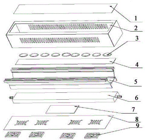
[0029] Such as figure 1 As shown, a distributed light source heat dissipation LED combination lamp in this embodiment includes: acrylic board 1, light box 2, LED bulb 3, PCB aluminum substrate 4, light groove 5, radiator 6, circuit board 7, light box top cover 8. Fan 9;

[0030] The acrylic plate 1 completely covers the bottom of the light box 2;

[0031] The LED bulb 3 is located inside the light box 2;

[0032] The lamp groove 5 is composed of two inner grooves;

[0033] The PCB aluminum substrate 4 is located on the top of the LED bulb 3 and is stuck in an inner groove of the lamp groove 5;

[0034] The radiator 6 is stuck in another inner groove of the lamp groove 5;

[0035] The circuit board 7 is located between the radiator 6 and the light box top cover 8;

[0036] The fan 9 is located outside the light box top cover 8 .

[0037] Both sides of the light box 2 are provided with light-transmitting holes.

[0038] There are at ...


PUM


Abstract

The invention discloses a dispersed light source radiating type LED assembled lamp. The dispersed light source radiating type LED assembled lamp comprises an acrylic sheet, a lamp box, an LED lamp bulb, a PCB aluminum base board, a lamp trough, a radiator, a circuit board, a lamp box top cover and a fan; the acrylic sheet completely covers the bottom part of the lamp box; the LED lamp bulb is positioned in the lamp box; the lamp trough comprises two inner concave grooves; the PCB aluminum base board is positioned on the top part of the LED lamp bulb and clamped into one of the inner concave grooves of the lamp trough; the radiator is clamped into another inner concave groove of the lamp trough; the circuit board is positioned between the radiator and the lamp box top cover; the fan is positioned at the outer side of the lamp box top cover. The dispersed light source radiating type LED assembled lamp is reasonable in design; the light sources are dispersed; the lamp bulb and a power supply can be radiated; therefore, the service life and safety of the LED lamp can be prolonged and improved.

Description

technical field [0001] The invention relates to the field of energy saving and environmental protection, in particular to a dispersed light source heat dissipation type LED combination lamp. Background technique [0002] At present, a kind of scattered light source heat dissipation LED lamp in the prior art mostly uses a light bulb or a lamp tube, or a spiral shape, or a column shape, and then realizes the purpose of dispersing the light source through the design of the lampshade, but all light sources are Concentrating on one light bulb, when one light bulb is damaged, it will cause no lighting in a short period of time, which will bring inconvenience to daily life, and even if the design of scattered light sources on the lampshade is a waste of cost, because there is only one light source, it still cannot completely solve the problem of light source. The problem of too much concentration will lead to the disadvantage of too weak lighting; in addition, due to the dense pop...

Claims


Application Information

Patent Timeline
Patent Type & Authority Applications(China)
IPC IPC(8): F21S2/00F21V29/51F21V29/67F21V31/00F21V19/00F21Y101/02
CPCF21K9/20F21V19/001F21Y2101/00
Inventor 陈金生
Owner 南通奥特机械设备有限公司
Learn More