Eureka AIR delivers breakthrough ideas for toughest innovation challenges, trusted by R&D personnel around the world.

Lawn lighting LED lamp

A technology of LED lamps and LED lighting lamps, applied in outdoor lighting, energy-saving lighting, lighting devices, etc., can solve the problems of low energy utilization rate, high power consumption, and inability to fully meet the power supply requirements of LED lamps for lawn lighting

Inactive Publication Date: 2015-04-29
SUZHOU KUNK & SAM LIGHTING TECH CO LTD
View PDF11 Cites 5 Cited by
  • Summary
  • Abstract
  • Description
  • Claims
  • Application Information

AI Technical Summary

Problems solved by technology

[0003] With the popularity of LED lamps, all kinds of lighting equipment based on LED lights have been promoted and popularized, especially in the night lighting of parks and green spaces and urban landscapes. The lighting is very popular in the market, but in use, it is found that the currently used LED lights for lawn lighting often need to lay long cables when power supplying, so the power supply cost is high, and the LED lights for lawn lighting also need to be used when running. It consumes more electric energy. In order to overcome this problem, there are currently solar power generation systems installed on LED lights for lawn lighting. However, solar power generation systems are greatly affected by the natural environment, and the energy utilization rate is relatively low. Meet the needs of power supply for LED lights for lawn lighting

Method used


Image

  • Lawn lighting LED lamp

Examples


Embodiment Construction

[0015] In order to make the technical means, creative features, goals and effects achieved by the present invention easy to understand, the present invention will be further described below in conjunction with specific embodiments.

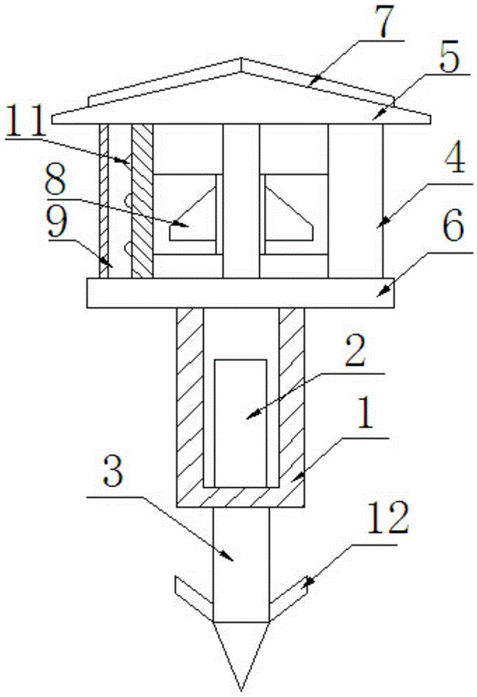
[0016] Such as figure 1 The LED lamp for lawn lighting includes a lamp base and a lamp body 1, the lamp base is connected to the front end of the lamp body 1 through threads, a battery 2 is arranged inside the lamp body 1, a pre-embedded nail 3 is arranged at the outer end of the lamp body 1, and the lamp base includes a column 4. Top cover 5, base 6, solar panel 7 and wind power generator 8, wherein there are at least three columns 4, and the first and last ends are respectively connected with the top cover 5 and the base 6, wherein the top cover 5 and the base 6 are coaxially distributed, And the column is evenly distributed with the top cover 5 symmetrical axis, the solar panel 7 is located on the upper surface of the top cover 5, the wind pow...


PUM


Abstract

The invention relates to a lawn lighting LED lamp comprising a lamp holder and a lamp body. The lamp holder is connected with the front end of the lamp body through threads. The lamp body is internally provided with an accumulator. An embedded nail is arranged at the tail of the lamp body. The lamp holder comprises at least three vertical columns, a top cover, a base, a solar cell panel and a wind driven generator. The tops and tails of the vertical columns are connected with the top cover and the base, respectively. The top cover and the base are co-axially distributed. The vertical columns are symmetrically distributed with the top cover as the axis. The solar cell panel is arranged on the upper surface of the top cover. The wind driven generator is arranged between the top cover and the base and connected with the vertical columns. Mounting grooves are formed in the surfaces of the vertical columns. Each mounting groove is internally provided with at least three LED lamps and covered with dimming lens. The solar cell panel, the wind driven generator and the LED lamps are all connected with the accumulator. The lawn lighting LED lamp is simple in structure, stable in lighting effect, wide in range of energy sources, high in utilization rate and low in lighting consumption.

Description

[0001] technology and [0002] The invention relates to an LED lamp for lawn lighting, which belongs to the technology of LED lighting and indicating equipment. Background technique [0003] With the popularity of LED lamps, all kinds of lighting equipment based on LED lights have been promoted and popularized, especially in the night lighting of parks and green spaces and urban landscapes. The lighting is very popular in the market, but in use, it is found that the currently used LED lights for lawn lighting often need to lay long cables when power supplying, so the power supply cost is high, and the LED lights for lawn lighting also need to be used when running. It consumes more electric energy. In order to overcome this problem, there are currently solar power generation systems installed on LED lights for lawn lighting. However, solar power generation systems are greatly affected by the natural environment, and the energy utilization rate is relatively low. It meets the p...

Claims


Application Information

Patent Timeline
Patent Type & Authority Applications(China)
IPC IPC(8): F21S9/02F21S9/03F21S9/04F21V21/08F21V5/04F21V23/00F21W131/109F21Y101/02
CPCY02B20/72F21K9/20F21S9/037F21S9/043F21V5/04F21V21/0824F21W2131/109F21Y2101/00
Inventor 傅立铭
Owner SUZHOU KUNK & SAM LIGHTING TECH CO LTD
Why Eureka
Eureka Blog
Learn More