Frequency modulation device for combustion gas turbine flame tube and combustion gas turbine flame tube

A gas turbine and flame tube technology, which is applied in the combustion chamber, combustion method, combustion equipment, etc., can solve the problems of complex combustion chamber structure and other problems

Active Publication Date: 2015-04-29
CHINA UNITED GAS TURBINE TECH CO LTD
View PDF11 Cites 5 Cited by
  • Summary
  • Abstract
  • Description
  • Claims
  • Application Information

AI Technical Summary

Problems solved by technology

In the patent No. CN1615416, Alstom invented a new type of gas turbine combustion chamber structure. In order to attenuate the thermoacoustic vibration in the combustion chamber, at least one Helmholtz damper is arranged. The Helmholtz The damping volume of the zipper damper is connected to the combustion chamber through a channel, and the damping frequency of the Helmholtz damper can be adjusted, but the damper also needs an additional frequency adjustment mechanism for the Helmholtz damper So that the structure of the combustion chamber becomes complicated

Method used


Image

  • Frequency modulation device for combustion gas turbine flame tube and combustion gas turbine flame tube
  • Frequency modulation device for combustion gas turbine flame tube and combustion gas turbine flame tube
  • Frequency modulation device for combustion gas turbine flame tube and combustion gas turbine flame tube

Examples


Embodiment 1

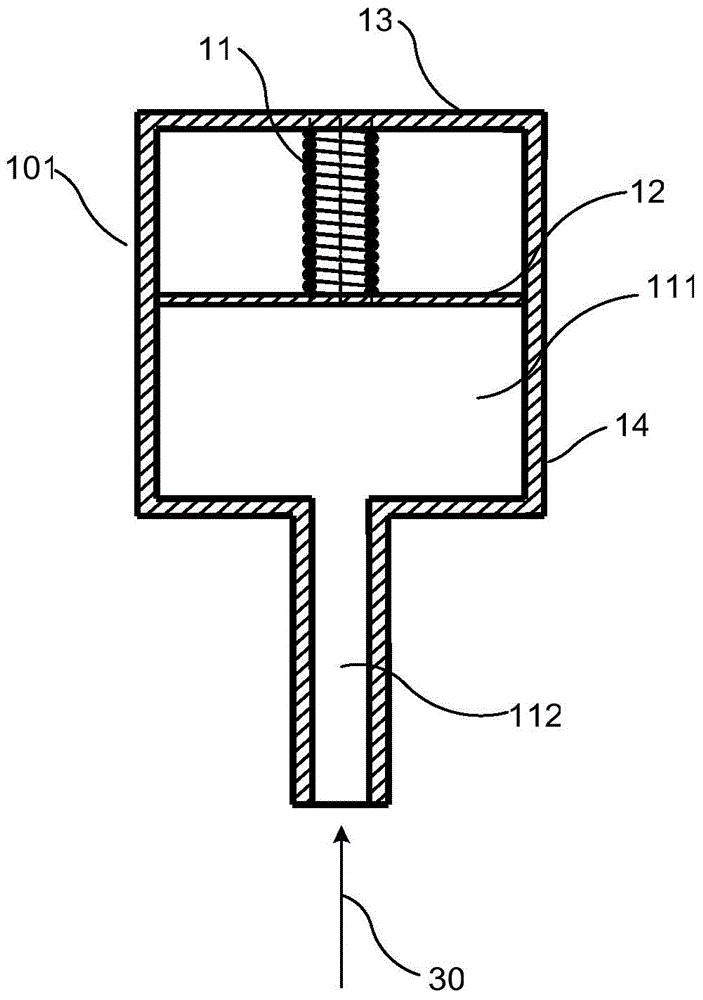
[0026] Such as figure 2 with image 3 As shown, a frequency modulation device 10 for a gas turbine flame cylinder provided by the present invention includes a device body, the device body is provided with a chamber, and the bottom of the chamber is provided with an opening for gas circulation, and the combustion gas flow 30 enters the chamber from the opening, the chamber is provided with an elastic element 11 and a partition 12 below the elastic element 11, the elastic element 11 can be various types of springs, one end of the elastic element 11 is connected to The top wall 13 of the chamber is connected, and the other end thereof is connected with the partition 12 , and there is a gap between the side of the partition 12 and the side wall 14 of the chamber. The frequency modulation device 10 is an acoustic chamber that oscillates the pressurized fluid at a specific frequency. The geometric configuration of the frequency modulation device 10 is directly related to the frequ...

Embodiment 2

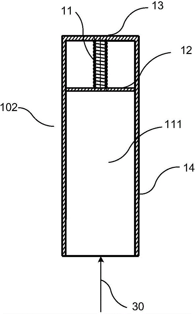
[0034] The difference between this embodiment and Embodiment 1 is that the device body uses a quarter-wavelength tube resonator 102, such as image 3 As shown, the quarter wave tube resonator 102 has a body cavity 111 . The relationship between the resonant frequency f of the quarter-wavelength tube resonator 102 and its geometric parameters is as follows:

[0035] f = c 4 L

[0036] where c is the speed of sound in a fluid (eg, air, fuel, or diluent) and L is the length of the quarter-wave tube resonator 102 . It can be seen that the quarter wave tube resonator 102 can attenuate frequencies corresponding to wavelengths four times its length L. FIG.


PUM


Abstract

The invention relates to the technical field of combustion gas turbines, and discloses a frequency modulation device for a combustion gas turbine flame tube. The frequency modulation device includes a device body which is provided with a cavity, wherein the bottom of the cavity is provided with an opening for air circulation, an elastic element and a baffle positioned below the elastic element are arranged in the cavity, one end of the elastic element is connected with the top wall of the cavity while the other end of the elastic element is connected with the baffle, and a gap is reserved between the side of the baffle and the side wall of the cavity; the invention also provides a combustion gas turbine flame tube, including a flame tube wall on which a plurality of frequency modulation devices for the combustion gas turbine flame tube according to the above technical scheme is arranged, wherein the cavities of the frequency modulation devices communicate with the flame tube wall to facilitate the circulation of combustion gas flow. The frequency modulation device for the combustion gas turbine flame tube can achieve stepless regulation on resonant frequency in the frequency modulation device, to automatically damp or inhibit thermo-acoustic vibration within a specific frequency band in the flame tube.

Description

technical field [0001] The invention relates to the technical field of gas turbines, in particular to a frequency modulation device for a gas turbine flame tube and a gas turbine flame tube. Background technique [0002] Gas turbines are developing towards high power, high efficiency, low emissions, fuel diversification and long life. Its development trend is concentrated in: increasing the pressure ratio of the compressor and the initial temperature of the turbine inlet to improve the overall performance of the gas turbine; broadening the fuel adaptability of the combustion chamber to achieve efficient and low-carbon utilization of various energy sources; adopting advanced combustion technology to reduce pollution To meet the requirements of environmental protection, the emission of waste is reduced; the efficiency of components and the whole machine is continuously improved by adopting advanced design technology; developing new high-temperature materials and adopting advan...

Claims


Application Information

Patent Timeline
IPC IPC(8): F23R3/42
Inventor 谢法
Owner CHINA UNITED GAS TURBINE TECH CO LTD
Why Eureka
Try Eureka