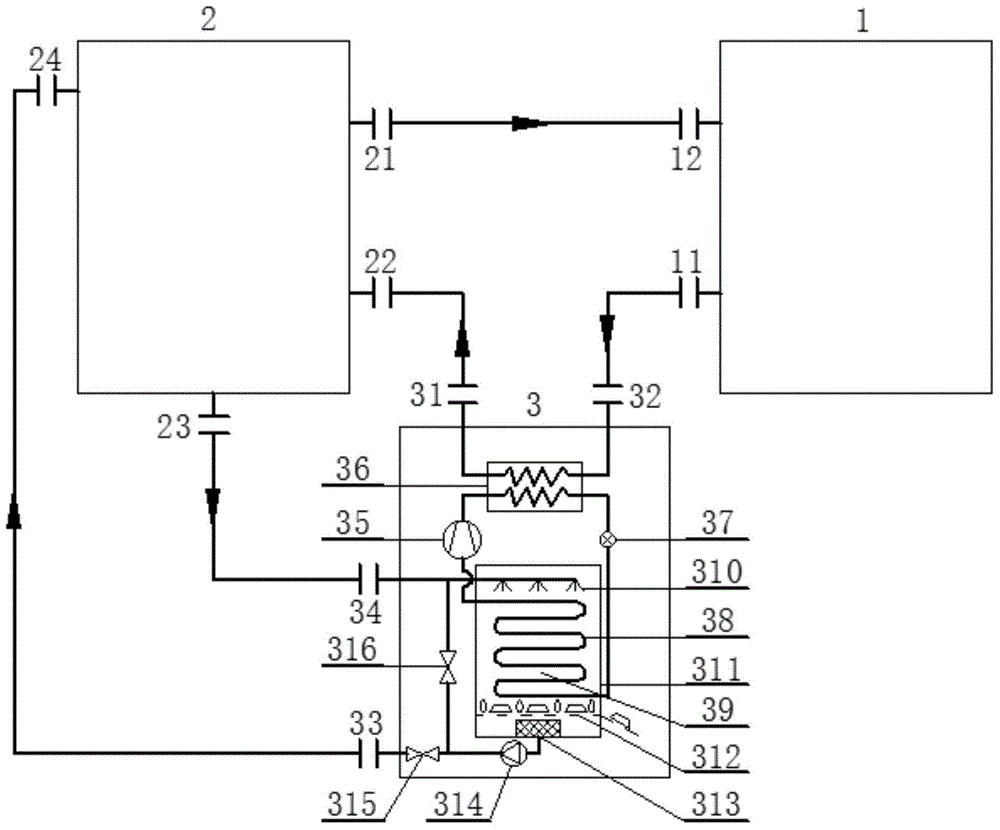
Solution heat pump system based on freezing regeneration and heat recovery thereof
A solution heat pump and heat recovery technology, used in heat recovery systems, heat pumps, refrigeration and liquefaction, etc., can solve problems such as increased energy consumption, reduce investment and land occupation, reduce solution usage, and achieve high efficiency.
- Summary
- Abstract
- Description
- Claims
- Application Information
AI Technical Summary
Problems solved by technology
Method used
Image
Examples
Embodiment 1
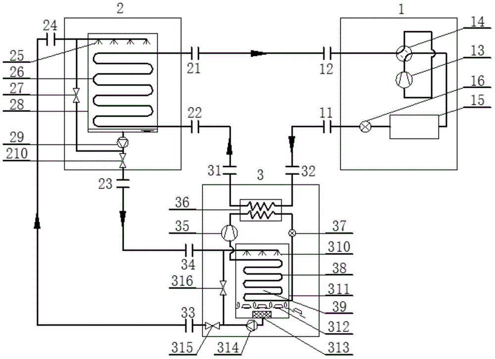
[0036] image 3 It is a structural principle diagram of the first embodiment of a solution heat pump system based on freezing regeneration and heat recovery provided by the present invention. It includes a user-side unit 1, an energy tower unit 2 and a refrigeration solution regeneration unit 3. The user-side unit 1 includes a working fluid outlet 11, a working fluid inlet 12, a second compressor 13, a four-way valve 14, and a user-side Heat exchanger 15 and second throttle valve 16; described energy tower unit 2 comprises working medium outlet 21, working medium inlet 22, solution outlet 23, solution inlet 24, solenoid valve 27, spray heat exchanger 28, Second solution pump 29, solenoid valve 210; described refrigeration solution regeneration unit 3 includes working medium outlet 31, working medium inlet 32, solution outlet 33, solution inlet 34, first compressor 35, first throttle valve 37 , Freezing regeneration ice tank 39, first solution pump 314, electromagnetic valve 3...
Embodiment 2
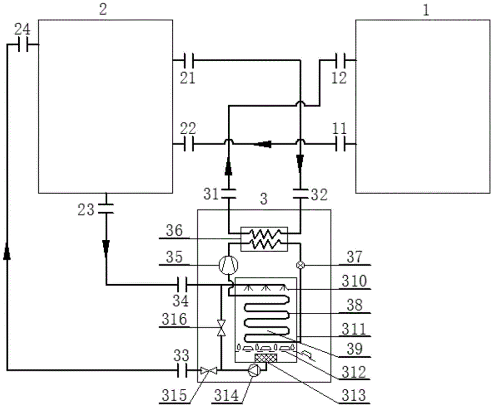
[0044] Figure 4 It is a structural principle diagram of the second embodiment of a solution heat pump system based on freezing regeneration and heat recovery provided by the present invention. It includes a user-side unit 1, an energy tower unit 2 and a refrigeration solution regeneration unit 3. The user-side unit 1 includes a working fluid outlet 11, a working fluid inlet 12, a second compressor 13, a four-way valve 14, and a user-side Heat exchanger 15 and second throttle valve 16; described energy tower unit 2 includes working fluid outlet 21, working fluid inlet 22, solution outlet 23, solution inlet 24, third solenoid valve 27, spray heat exchanger 28. The second solution pump 29, the fourth solenoid valve 210; the refrigeration solution regeneration unit 3 includes a working fluid outlet 31, a working fluid inlet 32, a solution outlet 33, a solution inlet 34, a first compressor 35, a first Throttle valve 37, frozen regenerated ice tank 39, first solution pump 314, fir...
Embodiment 3
[0047] Figure 5 It is a structural principle diagram of the third embodiment of a solution heat pump system based on freezing regeneration and heat recovery provided by the present invention. It includes a user-side unit 1, an energy tower unit 2 and a refrigeration solution regeneration unit 3. The user-side unit 1 includes a working fluid outlet 11, a working fluid inlet 12, a second compressor 13, a four-way valve 14, and a user-side Heat exchanger 15, second throttle valve 16, brine heat exchanger 17 and brine solution pump 18; the energy tower unit 2 includes a working medium outlet 21, a working medium inlet 22, a solution outlet 23, a solution Inlet 24, the third solenoid valve 27, spray heat exchanger 28, the second solution pump 29, the fourth solenoid valve 210; the freezing method solution regeneration unit 3 includes working medium outlet 31, working medium inlet 32, solution Outlet 33, solution inlet 34, first compressor 35, first throttle valve 37, frozen recyc...
PUM
 Abstract
Description
Claims
Application Information
 - R&D
- Intellectual Property
- Life Sciences
- Materials
- Tech Scout
- Unparalleled Data Quality
- Higher Quality Content
- 60% Fewer Hallucinations
Browse by: Latest US Patents, China's latest patents, Technical Efficacy Thesaurus, Application Domain, Technology Topic, Popular Technical Reports.
© 2025 PatSnap. All rights reserved.Legal|Privacy policy|Modern Slavery Act Transparency Statement|Sitemap|About US| Contact US: help@patsnap.com


