Electronic device and reception control method

A technology of electronic equipment and receiving control, which is applied in the direction of radio wave measurement system, satellite radio beacon positioning system, measuring device, etc., and can solve the problems of receiving and processing waste of power consumption, inability to use sufficient time, insufficient battery remaining, etc.

Active Publication Date: 2015-04-29
SEIKO EPSON CORP
View PDF11 Cites 2 Cited by
  • Summary
  • Abstract
  • Description
  • Claims
  • Application Information

AI Technical Summary

Problems solved by technology

[0005] When the above-mentioned device is operated with a portable battery-driven power source, since the power consumption of the receiving process is wasted, there is a problem that when the user wants to use the device for positioning, the remaining battery is insufficient and cannot be used for a sufficient time.

Method used


Image

  • Electronic device and reception control method
  • Electronic device and reception control method
  • Electronic device and reception control method

Examples


Deformed example 1

[0183] use Figure 7 illustrate.

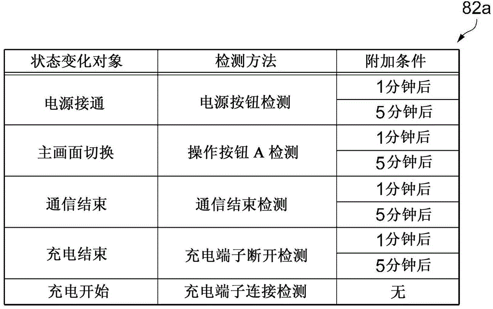
[0184] In the above-mentioned embodiment, the configuration in which each item of the predefined state change object and detection method is stored in the operation state data 82 and the sensor state data 84 has been described, but the configuration is not limited to this configuration.

[0185] A configuration may be adopted in which the processing unit 50 adds and changes new items of state change objects and detection methods from the personal computer and the server to the operation state data 82 and the sensor state data 84 via the communication unit 62 .

[0186] According to this modification, since it is possible to add and change state change objects and detection methods that were not initially assumed, it is possible to respond to new environments and new behavior patterns, and as a result, it is possible to improve the reception success rate of satellite signals.

Deformed example 2

[0188] Figure 10 It is a figure which shows an example of the state change concerning modification 2.

[0189] In the above-mentioned embodiments and modifications, the state change objects and detection methods for various usage patterns from a wide range of user classes were used, but it is also possible to use Each item unique to the user of the usage status.

[0190] Figure 10 in, to image 3 An example of an item of P(R|C) is added.

[0191] P(R|C) is a numerical value that shows the actual performance of receiving R and succeeding when the state change detection C is executed after the occurrence of the state change detection C. It is the denominator of the state change detection C. R is received and the number of successes is calculated as a fraction of the numerator. The magnitude of the numerical value of P(R|C) shows the degree to which the state change of the state change detection C depending on the user's action actually affects the reception success. That...

Deformed example 3

[0196] use image 3 as well as Figure 4 Be explained.

[0197] In the above-mentioned embodiment and modifications, as image 3 as well as Figure 4 As shown, although it is set to execute the signal reception R for each item, it is also possible to combine a plurality of items. For example, when the two conditions are combined in the order of "power on" and "illuminance", state change detection C occurs and signal reception R is executed under the condition "illuminance exceeds 100 after power on".

[0198] In this way, by referring to the reception success rate combining a plurality of state change objects, it is possible to discriminate a specific behavior pattern having a high reception success rate. Thereafter, if signal reception R is performed after detecting a specific behavior pattern, reception can be made successful with a high probability.


PUM


Abstract

An electronic device includes: a satellite signal receiving section that receives a satellite signal with which positioning information is overlapped from a positioning satellite; a reception control section that controls driving of the satellite signal receiving section; and a detecting section that detects a state change of the electronic device, in which the reception control section allows the satellite signal receiving section to enter a driving state when the detecting section detects the state change to receive the satellite signal. According to this electronic device, it is possible to reduce a TTFF at the positioning start, and to reduce power consumption in the satellite signal reception.

Description

technical field [0001] The invention relates to electronic equipment for receiving satellite signals from positioning satellites and performing positioning, and a receiving control method. Background technique [0002] It is known that there are opportunities to increase the acquisition of positioning information such as ephemeris contained in satellite signals sent from GNSS (Global Navigation Satellite System) satellites, and to shorten the time to first fix (TTFF: Time to First Fix, from connecting satellites The time from the power supply of the signal receiver to the output of the position information) technology. Positioning information has a service life, and in order to perform correct positioning in a positioning device, it is necessary to keep positioning information that has not expired. In the device shown in Patent Document 1 below, satellite signals are received from GNSS satellites and positioning information is acquired again at a certain time interval befor...

Claims


Application Information

Patent Timeline
Patent Type & Authority Applications(China)
IPC IPC(8): G01C23/00G01S19/14G04B47/06
CPCG01S19/34G01S19/19
Inventor 富井拓也佐藤礼子
Owner SEIKO EPSON CORP
Why Eureka
Try Eureka