
Testing device based on FPGA (field programmable gate array)

A test device and test data technology, applied in the direction of measurement device, electronic circuit test, measurement of electricity, etc., can solve the problems of high manufacturing cost, difficult miniaturization, high power, etc., to improve performance and integration, reduce power consumption, The effect of reducing line power consumption

Inactive Publication Date: 2015-04-29
SHENZHEN AID TECH
View PDF6 Cites 10 Cited by
  • Summary
  • Abstract
  • Description
  • Claims
  • Application Information

AI Technical Summary

Problems solved by technology

It aims to solve the problems of excessive power, difficulty in miniaturization, and high manufacturing cost of existing integrated circuit testing equipment

Method used


Image

  • Testing device based on FPGA (field programmable gate array)
  • Testing device based on FPGA (field programmable gate array)
  • Testing device based on FPGA (field programmable gate array)

Examples


Embodiment Construction

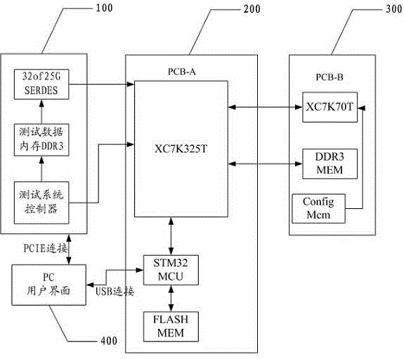
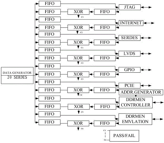
[0027] The present invention provides a testing device based on FPGA. In order to make the purpose, technical solution and effect of the present invention clearer and clearer, the present invention will be further described in detail below. It should be understood that the specific embodiments described here are only used to explain the present invention, not to limit the present invention.

[0028] The normal application of FPGA (Field-Programmable Gate Array) is to install it on a fixed circuit board, and the circuit components connected to it are fixed. The input and output standards and modes of the FPGA are set according to the performance standards of the components connected to it, and do not need to be changed at any time.

[0029] The present invention has utilized FPGA, and its circuit can be changed according to the demand of different tested components and its line, input and output standards, time delay and mode can be set to the corresponding standards and This ...


PUM


Abstract

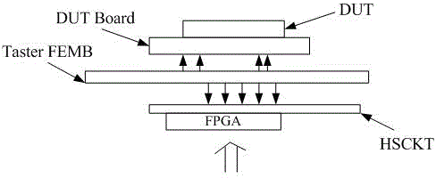
The invention discloses a testing device based on FPGA (field programmable gate array). The corresponding testing device which is designed innovatively through an FPGA circuit and adjustability of an output and input standard and a mode replaces corresponding electronic circuits of an existing testing device. The performance is greatly improved, and meanwhile, the power consumption of the circuit and the physical size and the cost of key design are greatly reduced. Additionally, the high-speed data transmission performance of the FPGA is innovatively used for transmitting a large quantity of test data to a device directly connected with a tested element at a high speed, and one of the bottlenecks of miniaturization of the key design is eliminated. Further, a circuit related with a direct-current and low-speed performance test and a high-speed test circuit are completely separated and are connected with the tested element during the test of each of the circuits, so the two circuits are not mutually influenced; the circuits are connected when the circuits need to be connected together for a corresponding test. Therefore, the power consumption, the physical size and the cost are greatly reduced, and the testing device has a good market popularization and utilization prospect.

Description

technical field [0001] The present invention relates to the technical field of electronic testing, and more specifically, to an FPGA-based testing device. Background technique [0002] The integrated circuit testing equipment includes a circuit for driving the device under test and receiving the output signal of the device under test. In the prior art, it is realized with specially designed special electronic devices. It has the following disadvantages: [0003] 1. Because it is specially designed and manufactured for this purpose, its usage is small, so the design and manufacturing costs are extremely high; [0004] 2. Because the driving and receiving voltages are continuously controllable and adjustable, it is very difficult to achieve high speed, and due to the large power consumption, it cannot be miniaturized due to heat dissipation. [0005] In addition, the controllable delay circuit used to adjust the timing of each channel in the prior art uses split elements, w...

Claims


Application Information

Patent Timeline
Patent Type & Authority Applications(China)
IPC IPC(8): G01R31/28G01R31/00
Inventor 陆放
Owner SHENZHEN AID TECH
Learn More