Voltage regulator circuit and method thereof
A voltage regulator circuit and voltage technology, applied in the direction of regulating electrical variables, control/regulating systems, instruments, etc., can solve problems such as inability to have overcurrent and short-circuit current protection capabilities at the same time, increase power loss, and slowly restore normal working conditions.
- Summary
- Abstract
- Description
- Claims
- Application Information
AI Technical Summary
Problems solved by technology
Method used
Image
Examples
Embodiment Construction
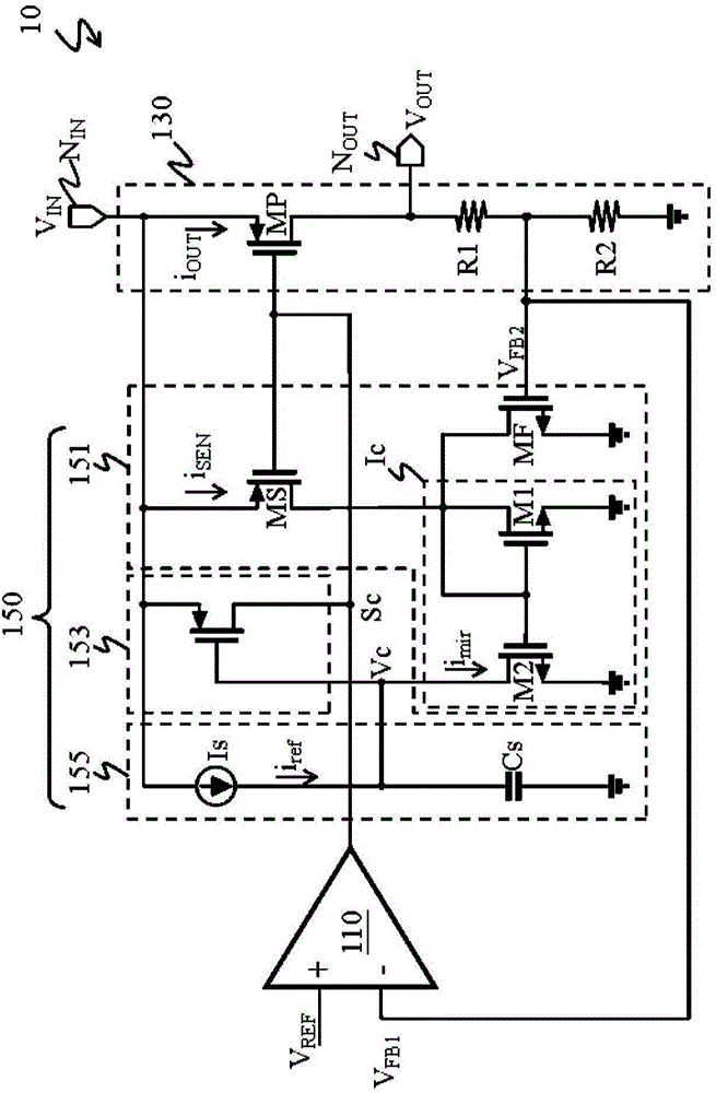
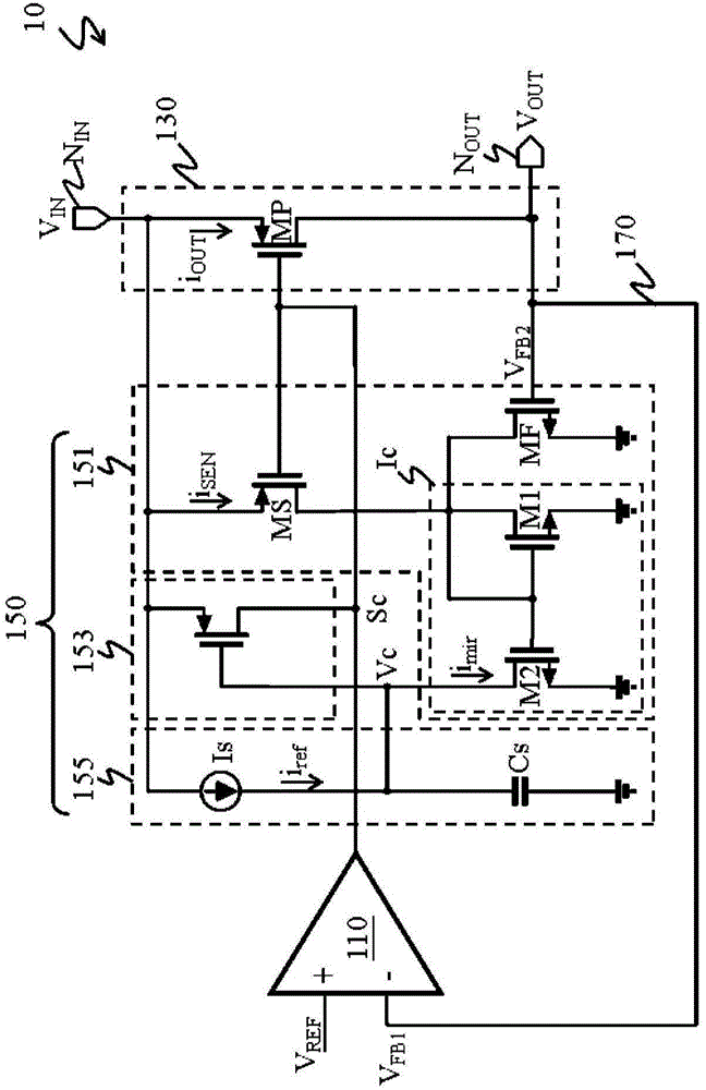
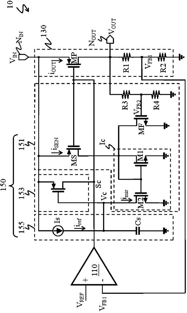
[0049] refer to figure 1 , The voltage stabilizing circuit 10 includes: an error amplifier 110 , an output circuit 130 and an overcurrent protection circuit 150 .
[0050] The overcurrent protection circuit 150 includes a current sensing circuit 151 , a protection switch 153 and a judgment circuit 155 . The current sensing circuit 151 includes a sensing element MS and a variable current source Ic.
[0051] The output terminal of the error amplifier 110 is electrically connected to the output circuit 130 and the control terminal of the sensing element MS. The input end of the output circuit 130 is electrically connected to the power contact N IN , and the output terminal of the output circuit 130 is electrically connected to the load contact N OUT .
[0052] Here, the output circuit 130 includes a power element MP. The power element MP has a first terminal, a second terminal and a control terminal. The control terminal of the power element MP and the control terminal of t...
PUM
 Abstract
Description
Claims
Application Information
 - R&D
- Intellectual Property
- Life Sciences
- Materials
- Tech Scout
- Unparalleled Data Quality
- Higher Quality Content
- 60% Fewer Hallucinations
Browse by: Latest US Patents, China's latest patents, Technical Efficacy Thesaurus, Application Domain, Technology Topic, Popular Technical Reports.
© 2025 PatSnap. All rights reserved.Legal|Privacy policy|Modern Slavery Act Transparency Statement|Sitemap|About US| Contact US: help@patsnap.com


