
Parking space identification method and device by using laser light knife as auxiliary light source

A parking space recognition and auxiliary light source technology, applied in the field of parking space recognition, can solve the problems of multiple devices and complex image processing algorithms, and achieve the effect of reducing lighting conditions and simple and reliable image processing algorithms

Active Publication Date: 2015-04-29
XI AN JIAOTONG UNIV +1
View PDF5 Cites 5 Cited by
  • Summary
  • Abstract
  • Description
  • Claims
  • Application Information

AI Technical Summary

Problems solved by technology

The ultrasonic ranging method is to install an ultrasonic ranging probe above each parking space, and judge whether there is a vehicle parked under the probe by measuring the distance. This method is simple and reliable. The disadvantage is that an ultrasonic probe is required to be installed above each parking space.
The image recognition method uses a camera to capture an image and judges whether it is an empty parking space through digital image processing. This method can identify multiple parking spaces through a camera. The disadvantage is that the image processing algorithm is relatively complicated, and it also needs to meet certain lighting conditions.

Method used


Image

  • Parking space identification method and device by using laser light knife as auxiliary light source
  • Parking space identification method and device by using laser light knife as auxiliary light source
  • Parking space identification method and device by using laser light knife as auxiliary light source

Examples


Embodiment 1

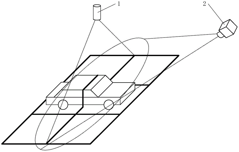
[0030] Such as figure 1 As shown, the parking space recognition device is composed of a laser light knife 1 , a camera 2 , a computer 3 and a display device 4 . The laser light knife 1 power supply can be turned on or off by computer 3 control.

[0031] Laser Light Knife 1 is a laser light source that emits a fan-shaped beam, such as figure 2 As shown, the laser light knife 1 is installed on the roof of the garage above a row of parking spaces to be detected, and the light knife forms a straight line on the ground, which traverses the row of parking spaces to be detected.

[0032] A narrow-band filter is installed on the lens of camera 2, which only allows light with the same wavelength as the light knife to pass through. Such as figure 2 As shown, the camera 2 is installed on the roof of the garage obliquely above a row of parking spaces to be detected, so that the light formed by the light knife on the ground is in the field of view of the camera 2.

[0033] The comput...

Embodiment 2

[0035] Such as figure 1 As shown, the parking space recognition device is composed of a laser light knife 1 , a camera 2 , a computer 3 and a display device 4 . The laser light knife 1 power supply can be turned on or off by computer 3 control.

[0036] Laser Light Knife 1 is a laser light source that emits a fan-shaped beam, such as Figure 4 As shown, a laser light knife 1 is installed above each row of parking spaces to be detected, and the light knife forms a straight line on the ground, and the straight line traverses a row of parking spaces to be detected.

[0037] A narrow-band filter is installed on the lens of camera 2, which only allows light with the same wavelength as the light knife to pass through. Such as Figure 4 As shown, the camera 2 is installed above the aisle between the two rows of parking spaces to be detected. The camera 2 adopts a wide-angle lens so that the light formed by two adjacent light knives on the ground is in the field of view of the came...


PUM


Abstract

The invention provides a parking space identification method and device by using a laser light knife as an auxiliary light source. The device is composed of the laser light knife, a camera, a computer and display equipment. When detection is needed, the computer gives out a control instruction first, the laser light knife is used for emitting a fan beam, and the fan beam is projected to a whole row of parking spaces to be detected to form a straight line beam which penetrates through the whole row of parking spaces transversely; the camera is used for collecting the beam images formed by the laser light knife on all the parking spaces, if one image is a section of straight line, it means that the corresponding parking space is vacant, and if the image is a section of arc placed above the straight line, it means that the corresponding parking space is occupied. The parking space identification device can be used for detecting one row of parking spaces, the image processing algorithm is simple and reliable, meanwhile, the requirement for lighting conditions is lowered, and normal detection can still be conducted even in an all-black underground parking garage.

Description

technical field [0001] The invention belongs to the technical field of position recognition, and in particular relates to a parking space recognition method and device using a laser light knife as an auxiliary light source. Background technique [0002] The automatic identification of empty parking spaces in the parking lot can improve the efficiency of parking lot management. At present, a variety of empty parking space identification methods have been applied. The commonly used methods are ultrasonic distance measurement and image recognition. The ultrasonic distance measuring method is to install an ultrasonic ranging probe above each parking space, and judge whether there is a vehicle parked under the probe by measuring the distance. The image recognition method uses a camera to capture an image and judges whether it is an empty parking space through digital image processing. This method can identify multiple parking spaces through a camera. The disadvantage is that the ...

Claims


Application Information

Patent Timeline
IPC IPC(8): G08G1/14
Inventor 乐开端易亚星
Owner XI AN JIAOTONG UNIV
Learn More