Electrostatic protection circuit

An electrostatic protection and circuit technology, which is applied in the design of integrated circuit electrostatic protection circuits and electrostatic protection circuit design, can solve the problems of high trigger voltage, influence of noise index on radio frequency circuit transmission coefficient, slow response speed, etc., and achieve low trigger voltage and high response Good effect of speed block and conduction uniformity

Inactive Publication Date: 2015-04-29
WUHAN XINXIN SEMICON MFG CO LTD
View PDF10 Cites 5 Cited by
  • Summary
  • Abstract
  • Description
  • Claims
  • Application Information

AI Technical Summary

Problems solved by technology

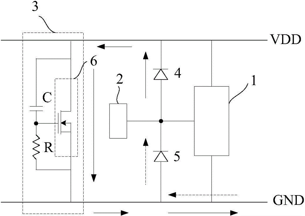
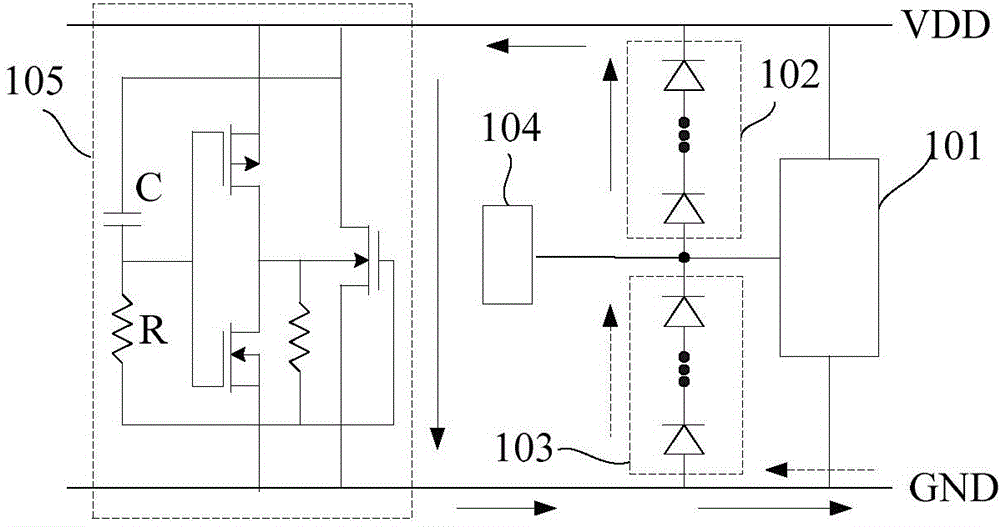
but, figure 2 The diode string structure in will introduce a large resistance in the circuit
[0005] but, figure 1 Gate-couple NMOS transistor 6, which is used in the clamping circuit figure 2 The substrate trigger (Sub-trigger) clamp circuit used in the clamp circuit has high trigger voltage, slow response speed, and poor conduction uniformity, which will affect the transmission coefficient (power gain) and noise figure (noise figure) of the radio frequency circuit ( noise figure) have an impact

Method used


Image

  • Electrostatic protection circuit
  • Electrostatic protection circuit
  • Electrostatic protection circuit

Examples


Embodiment Construction

[0030] The electrostatic protection circuit of the present invention will be described in more detail below in conjunction with schematic diagrams, wherein a preferred embodiment of the present invention is shown, and it should be understood that those skilled in the art can modify the present invention described here and still achieve the beneficial effects of the present invention. Therefore, the following description should be understood as the broad knowledge of those skilled in the art, but not as a limitation of the present invention.

[0031] In the following paragraphs the invention is described more specifically by way of example with reference to the accompanying drawings. Advantages and features of the present invention will be apparent from the following description and claims. It should be noted that all the drawings are in a very simplified form and use imprecise scales, and are only used to facilitate and clearly assist the purpose of illustrating the embodiment...


PUM


Abstract

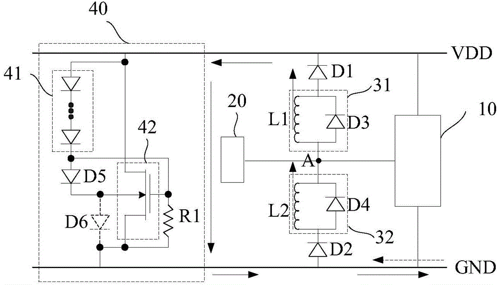
The invention provides an electrostatic protection circuit which comprises an input / output pin, a power output terminal, a ground terminal, a function unit and a clamping circuit. The function unit is connected with the power output terminal and the ground terminal, the clamping circuit is connected with the power output terminal and the ground terminal, the function unit is connected with the input / output pin through a node, a first unidirectional conducting unit is connected between the node and the power output terminal in series, and the node and the ground terminal are in series connection with a second unidirectional conducting unit; a first LC circuit is connected between the node and the power output terminal in series or a second LC circuit is connected between the node and the ground terminal in series, or the first LC circuit is connected between the node and the power output terminal in series and the second LC circuit is connected between the node and the ground terminal in series. The electrostatic protection circuit has the advantages of being high in response speed, low in trigger voltage, better in conducting uniformity, and capable of reducing the influence on radio-frequency signals of the function unit.

Description

technical field [0001] The invention relates to the design field of electrostatic protection circuits for integrated circuits, in particular to an electrostatic protection circuit design applied to radio frequency circuits. Background technique [0002] Integrated circuits are easily affected by electrostatic discharge (ESD) during manufacturing, assembly and testing or in final applications, so that integrated circuits are damaged by static electricity. [0003] References to electrostatic protection circuit diagrams for radio frequency circuits in the prior art figure 1 As shown, it includes radio frequency circuit 1, input / output pin 2, clamping circuit 3, power supply output terminal VDD and ground terminal GND. The output terminal VDD and the clamp circuit 3 are released to the ground terminal GND, and the current direction is as follows figure 1 Indicated by the solid arrow. When a negative electrostatic pulse is generated in the input / output pin 2, the charge is re...

Claims


Application Information

Patent Timeline
Patent Type & Authority Applications(China)
IPC IPC(8): H02H9/04
Inventor 单毅
Owner WUHAN XINXIN SEMICON MFG CO LTD
Why Eureka
Try Eureka