Ventilation steel channel, manufacturing method of ventilation steel channel, ventilation structure and motor

A ventilation channel steel and superior technology, which is applied in the field of ventilation structure, motor and ventilation channel steel, can solve the problems affecting the heat dissipation coefficient of the motor surface and local pressure drop, the difficulty of ventilation channel steel, and the influence on the temperature rise of the motor, etc., to achieve enhanced cooling and heat dissipation The effect of low manufacturing difficulty and low processing cost

Active Publication Date: 2015-04-29
BEIJING GOLDWIND SCI & CREATION WINDPOWER EQUIP CO LTD
View PDF9 Cites 1 Cited by
  • Summary
  • Abstract
  • Description
  • Claims
  • Application Information

AI Technical Summary

Problems solved by technology

[0005] The design of traditional ventilation channel steel and ventilation structure does not pay special attention to the influence of ventilation channel steel on the cooling effect of cooling gas
The traditional ventilation channel steel only plays the role of supporting and separating the ventilation trench between adjacent iron core segments, but the inventor found through analysis and thinking that the shape of the ventilation channel steel can have a great influence on the flow of cooling gas in the ventilation trench , determines the quality of the cooling performance of the motor, because the turbulence of the cooling gas flowing through the ventilation groove can be different under different shapes of the ventilation channel steel, which will affect the heat dissipation coefficient of the motor surface and the local pressure drop, and finally affect the motor performance. temperature rise
Therefore the shape design of the ventilation channel steel is a key technology, but simultaneously the design of the ventilation channel steel also needs to consider factors such as manufacturability, installation reliability and cost, which makes the design of the ventilation channel steel have certain difficulties. Channel steel plays an important role, but there are few studies on this aspect

Method used


Image

  • Ventilation steel channel, manufacturing method of ventilation steel channel, ventilation structure and motor
  • Ventilation steel channel, manufacturing method of ventilation steel channel, ventilation structure and motor
  • Ventilation steel channel, manufacturing method of ventilation steel channel, ventilation structure and motor

Examples


Embodiment 1

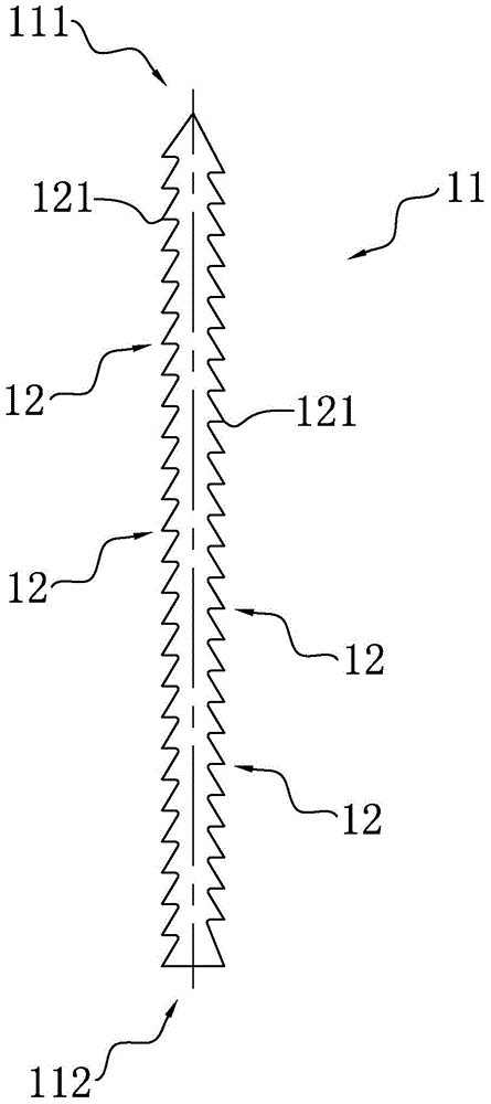
[0050] Such as figure 1 As shown, it is a schematic structural diagram of the ventilation channel steel in the first embodiment of the present invention. The ventilation channel steel of the first embodiment of the present invention includes a ventilation channel steel body 11, and at least one of the two opposite sides of the ventilation channel steel body 11 (for example, two as shown in the figure) is provided with a plurality of Tooth 12.

[0051] The ventilation channel steel of the first embodiment of the present invention is different from the commonly used traditional "I"-shaped ventilation channel steel and strip ventilation channel steel. The teeth 12 provided on the side of the ventilation channel steel body 11 can at least bring the following advantages:

[0052] 1. It can effectively break the boundary layer between the ventilation channel steel and the cooling gas flowing through the ventilation trench, significantly increase the turbulence of the cooling gas, and mak...

Embodiment 2

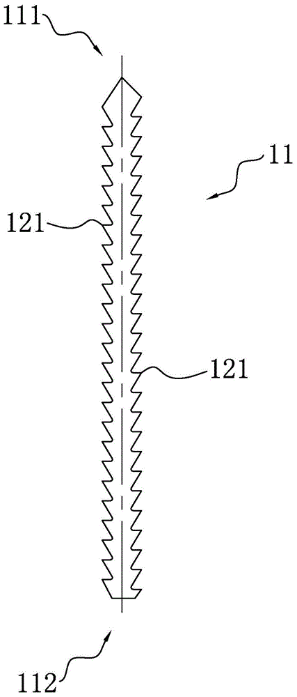
[0062] Such as figure 2 As shown, it is a schematic structural diagram of the ventilation channel steel in the second embodiment of the present invention. The teeth of the ventilation channel steel in this embodiment are also triangular teeth 121, and the tooth profile lines are also two line segments with common endpoints. The difference between the ventilation channel steel in this embodiment and the ventilation channel steel in the first embodiment is: these two The length of the line segment close to the upwind end 111 of the ventilation channel steel body 11 is smaller than the length of the line segment close to the downwind end 112 of the ventilation channel steel body 11, that is, the tip of the triangular tooth 121 is more toward the upstream side of the cooling gas, In this way, the collision area between the triangular teeth 121 and the cooling air can be effectively increased, a greater turbulence effect is generated, and the width of the airflow in a high turbulenc...

Embodiment 3

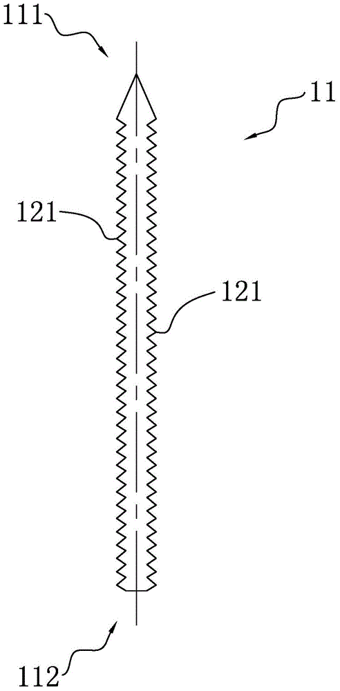
[0064] Such as image 3 As shown, it is a schematic structural diagram of a ventilation channel steel in the third embodiment of the present invention. The teeth of the ventilation channel steel in this embodiment are also triangular teeth 121, and the tooth profile lines are also two line segments with common endpoints. The main differences between the ventilation channel steel in this embodiment and the ventilation channel steel in the previous embodiment are: The length of the line segment close to the upwind end 111 of the ventilation channel steel body 11 among the line segments is equal to the length of the line segment close to the downwind end 112 of the ventilation channel steel body 11, that is, the tip of the triangular tooth 121 faces perpendicular to the ventilation channel steel body 11 This shape is a compromise shape of the tooth shape in the first and second embodiments. Compared with the first embodiment, it can produce a greater turbulence effect, and compared...


PUM


Abstract

The invention provides a ventilation steel channel, a manufacturing method of the ventilation steel channel, a ventilation structure and a motor. The ventilation steel channel provided by the invention comprises a ventilation steel channel body; a plurality of teeth are formed on at least one of two opposite lateral surfaces of the ventilation steel channel body. The ventilation structure provided by the invention comprises at least two iron core sections; the iron core sections are provided with a plurality of tooth parts; slots for accommodating windings are formed between the adjacent tooth parts on the same iron core sections; the ventilation steel channels are formed between the corresponding tooth parts of the adjacent iron core sections; the teeth of the ventilation steel channels face towards the slots. According to the ventilation steel channel provided by the invention, the teeth can effectively break through a boundary layer between the ventilation steel channel and cooling gas flowing through ventilation grooves, the heat dissipation area is increased, and cooling and heat dissipating effects are reinforced; meanwhile, the process of the ventilation steel channel is easy to realize with low manufacturing difficulty.

Description

Technical field [0001] The invention relates to the cooling of a motor, in particular to a ventilation channel steel, a manufacturing method thereof, a ventilation structure and a motor. Background technique [0002] When motors (including motors and generators) are running, energy loss will occur on coils, cores and other components. This loss will eventually be dissipated in the form of heat. If the ventilation design of the motor is unreasonable, it will cause the temperature of the motor to rise. Too high or uneven local temperature rise. Excessive temperature rise will lead to insulation aging, which will reduce the electrical performance of the insulation during long-term operation, and uneven local temperature rise will generate large thermal stress, resulting in permanent damage to the motor structure, and eventually motor failure. Therefore, reducing the temperature rise of the motor is of great significance for improving the safety margin of the motor, prolonging the s...

Claims


Application Information

Patent Timeline
Patent Type & Authority Applications(China)
IPC IPC(8): H02K1/20H02K1/32H02K15/02
CPCH02K1/20H02K1/325H02K15/02
Inventor 张新丽
Owner BEIJING GOLDWIND SCI & CREATION WINDPOWER EQUIP CO LTD
Why Eureka
Try Eureka