
Position-sensorless control method suitable for running of switched reluctance motor in whole-speed range

A technology of switched reluctance motor and control method, which is applied in the direction of single motor speed/torque control, AC motor control, control system, etc., and can solve the problem of limited application range, position sensorless control, and unfavorable optimal control of the full speed range of the motor And other issues

Inactive Publication Date: 2015-04-29
CHINA UNIV OF MINING & TECH
View PDF4 Cites 12 Cited by
  • Summary
  • Abstract
  • Description
  • Claims
  • Application Information

AI Technical Summary

Problems solved by technology

The disadvantage of these schemes is that they can only perform position sensorless control after the switched reluctance motor starts, and are not suitable for initial position positioning and position sensorless start when the switched reluctance motor is started, especially when the motor has a certain initial inertial speed. No reverse start
Therefore, it is not conducive to the optimal control of the motor's full speed range, which limits its scope of application.

Method used


Image

  • Position-sensorless control method suitable for running of switched reluctance motor in whole-speed range
  • Position-sensorless control method suitable for running of switched reluctance motor in whole-speed range
  • Position-sensorless control method suitable for running of switched reluctance motor in whole-speed range

Examples


Embodiment 1

[0043] Embodiment 1: The control method is based on the complex plane inductance model of the switched reluctance motor, and establishes the functional relationship between the rotor angle and the inductance coefficient and the three-phase inductance; when the motor is static or started under the condition of initial speed, the pulse injection method is used Obtain the three-phase inductance; when the motor is running at low speed, use the idle phase pulse injection method to establish the functional relationship of the sum of the three-phase inductance, so as to obtain the conduction phase inductance; when the motor is running at high speed, divide the integral flux linkage by the current to obtain Refer to the phase inductance; use the derived rotor position estimation analytical formula to calculate the current rotor position, and realize the position sensorless operation control of the switched reluctance motor according to the estimated rotor position.

[0044] A position ...

Embodiment 2

[0071] Embodiment 2: Take a 12 / 8-pole 15kw switched reluctance motor as an example, and describe it in detail with reference to the accompanying drawings.

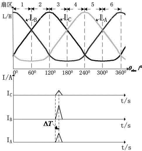
[0072] When the motor starts at rest, the injection time is ΔT, and the response current is ΔI k , the three-phase inductance value of the rotor at the initial position changes with the change of the three-phase response current amplitude, as shown in the attached figure 1 .

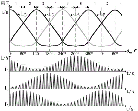
[0073] attached figure 2 It is the schematic diagram when the motor starts with the initial speed state. Since the motor rotor is in the rotating state, the three-phase response current amplitude will change periodically, and the response current amplitude of the winding is inversely proportional to the inductance, that is, at the maximum position of the inductance The corresponding response current value is the minimum; on the contrary, the response current amplitude reaches the maximum at the minimum inductance. It can be seen that the three-pha...


PUM


Abstract

The invention discloses a position-sensorless control method suitable for running of a switched reluctance motor in a whole-speed range, and belongs to control methods of switched reluctance motors. A function relationship among a rotor angle, an inductance coefficient and three phases of inductances is set up based on a complex plane induction model of the switched reluctance motor; when the switched reluctance motor is static or is started under the initial rotating speed condition, a pulse injection method is adopted to obtain the three phases of inductances; when the switched reluctance motor runs at the low speed, a free phase pulse injection method is adopted to set up a function relationship of the sum of the three phases of inductances, and therefore conduction phase inductances are obtained; when the switched reluctance motor runs at the high speed, current is divided by an integral magnetic chain, so that reference phase inductances are obtained; a rotor position obtained through derivation is utilized for estimating an analytic expression and calculating the current position of a rotor, and according to the estimated rotor position, the position-sensorless run control over the switched reluctance motor can be achieved. The method is simple and small in calculated amount, a controller can easily run in the whole-speed range, and the higher position estimation precision is achieved.

Description

technical field [0001] The invention relates to a control method of a switched reluctance motor, in particular to a position sensorless control method suitable for the full-speed operation of the switched reluctance motor. Background technique [0002] Switched reluctance motor (SRM) has the advantages of simple and firm structure, convenient and flexible control, and wide speed and power range. It is widely used in various fields such as traction transportation, general industry, aviation, and household appliances. One of the hot topics. The position detection link is an important part of the switched reluctance motor drive system. The detected position signal is not only the basis for turning on and off the winding, but also provides speed information for the closed-loop control of the speed. In current practical applications, shaft position sensors or other types of detection position detectors are generally used to obtain rotor position information. The introduction of ...

Claims


Application Information

Patent Timeline
IPC IPC(8): H02P6/08
CPCH02P25/089
Inventor 蒯松岩孙文兵马金洋王从庆汤锐智李兴红沈恂
Owner CHINA UNIV OF MINING & TECH
Learn More